Manufacturing method of scattered radiation removing grid

a radiation elimination grid and manufacturing method technology, applied in the direction of manufacturing tools, instruments, nuclear engineering, etc., can solve the problems of tension, no longer functional scattering x-ray elimination grid, and the point at which the holes of metal foils deform, so as to reduce the exposure dose of the subject, eliminate any difference in tension, and improve the transmission of primary x-rays

Inactive Publication Date: 2013-04-16
SHIMADZU CORP
View PDF12 Cites 7 Cited by
  • Summary
  • Abstract
  • Description
  • Claims
  • Application Information

AI Technical Summary

Benefits of technology

[0012]To solve the aforementioned problems, a method of manufacturing a scattered X-ray eliminating grid according to the present invention comprises the steps of: disposing guide slit plates such that they are fixed relative to one another, namely, parallel to and spaced apart from one another by a prescribed distance; forming numerous guide slits in each guide slit plate; fitting numerous metal foils, which serve as X-ray absorbing substance provided between the guide slit plates, in the numerous guide slits such that they are parallel to primary X-rays; inserting both ends of the metal foils into opposing guide slits of each of the guide slit plates and, in that state, holding the metal foils on the outer sides of the slits in the state wherein an urging means applies tension to one end or both ends of the metal foils; bonding thin plates, which are made of a light element and serve as grid covers, to an X-ray incident side and an X-ray emergent side of the metal foils such that the thin plates cover the metal foils; removing the urging means and a fixing means of the metal foils; cutting off both ends of each of the metal foils at inner sides of the guide slit plates; and removing the metal foils from the guide slit plates on both sides; wherein, to enable the urging means to exert tension evenly over all of the metal foils, a rod, which is sheathed in an elastic body, is inserted into holes, which are formed in the metal foils on the tip sides of the metal foils beyond the inserted portions, in the state wherein vicinities of both ends of the metal foils are inserted into the guide slits, and thereby the metal foils are held and pulled; and a structure is adopted that ensures that the cross sectional shape of the elastic body sheathing the rod has a sufficient wall thickness in a direction in which the elastic body is compressed, when tension is generated, which eliminates any difference in the tension even if a spring constant k that is determined during compression is small and the amounts of compression are different.
[0013]According to the scattered X-ray eliminating grid, manufacturing method of the present invention, in the state wherein both end of the numerous metal foils, which serve as the X-ray absorbing substance, are inserted into the guide slits of the guide slit plates, which are fixed, parallel to one another, thin plates (e.g., carbon fiber sheets, aluminum sheets, or the like), which are made of a light element, that serve as grid covers are bonded—in the state wherein the urging means has been used to correct the shape of each of the metal foils by evenly applying tension to one end or both ends of each of the metal foils—at the outer sides of the slits to a primary X-ray incident side and an X-ray emergent side of the metal foils such that the grid covers cover the metal foils, and, in that state, both ends of the metal foils are cut off at the inner sides of the guide slit plates, the metal foils to which the grid covers are bonded are removed, and thereby a grid is achieved wherein air serves as the intermediate substance; therefore, compared with the case wherein aluminum, fiber, or the like is used as the intermediate substance, the transmittance of the primary X-rays can be improved and the exposure dose of the subject can be reduced, commensurately.
[0014]In addition, according to the scattered X-ray eliminating grid manufacturing method of the present invention, even if a relatively low strength material, such as lead, a lead alloy, copper, a copper alloy, iron, a ferrous alloy, or nickel, or a material of a similar strength is selected as the thin metal foil material that serves as the X-ray absorbing substance, the holes of the metal foils do not deform because the rod can be inserted into the holes of the metal foils and evenly pulled, the positioning and the shape of the metal foils can be corrected reliably, and a scattered X-ray eliminating grid wherein air serves as the intermediate substance can be manufactured stably and inexpensively.

Problems solved by technology

Namely, because the tension is expressed by the equation F=kx, tension cannot be exerted, evenly over all of the metal foils if the spring constant k is large and there is variation in the hole-to-hole spacing of the metal foils, which is a problem.
Consequently, the scattered X-ray eliminating grid is no longer functional because, even in the tensioned state, some of the metal foils extend perfectly straight while some are deformed, namely, curved.
However, if a comparatively weak material—such as lead, a lead alloy, copper, a copper alloy, iron, a ferrous alloy, or nickel—or a material of a similar strength is selected as the material of the metal foils, then the limit point at which the holes of the metal foils will deform when the rods are inserted and pulled therethrough will be low and differentially large tensions will be exerted if the hole-to-hole spacing of the metal foils is short; thereby, the holes will deform, it will no longer be possible to apply tension properly and, in the worst case, the metal foils will sever.

Method used


Image

  • Manufacturing method of scattered radiation removing grid
  • Manufacturing method of scattered radiation removing grid
  • Manufacturing method of scattered radiation removing grid

Examples


Embodiment Construction

[0020]An embodiment of the present invention is explained below, referencing the drawings.

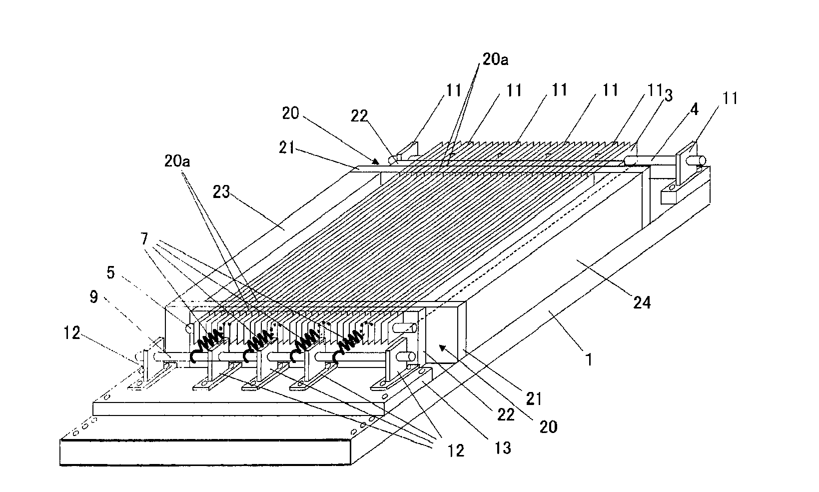
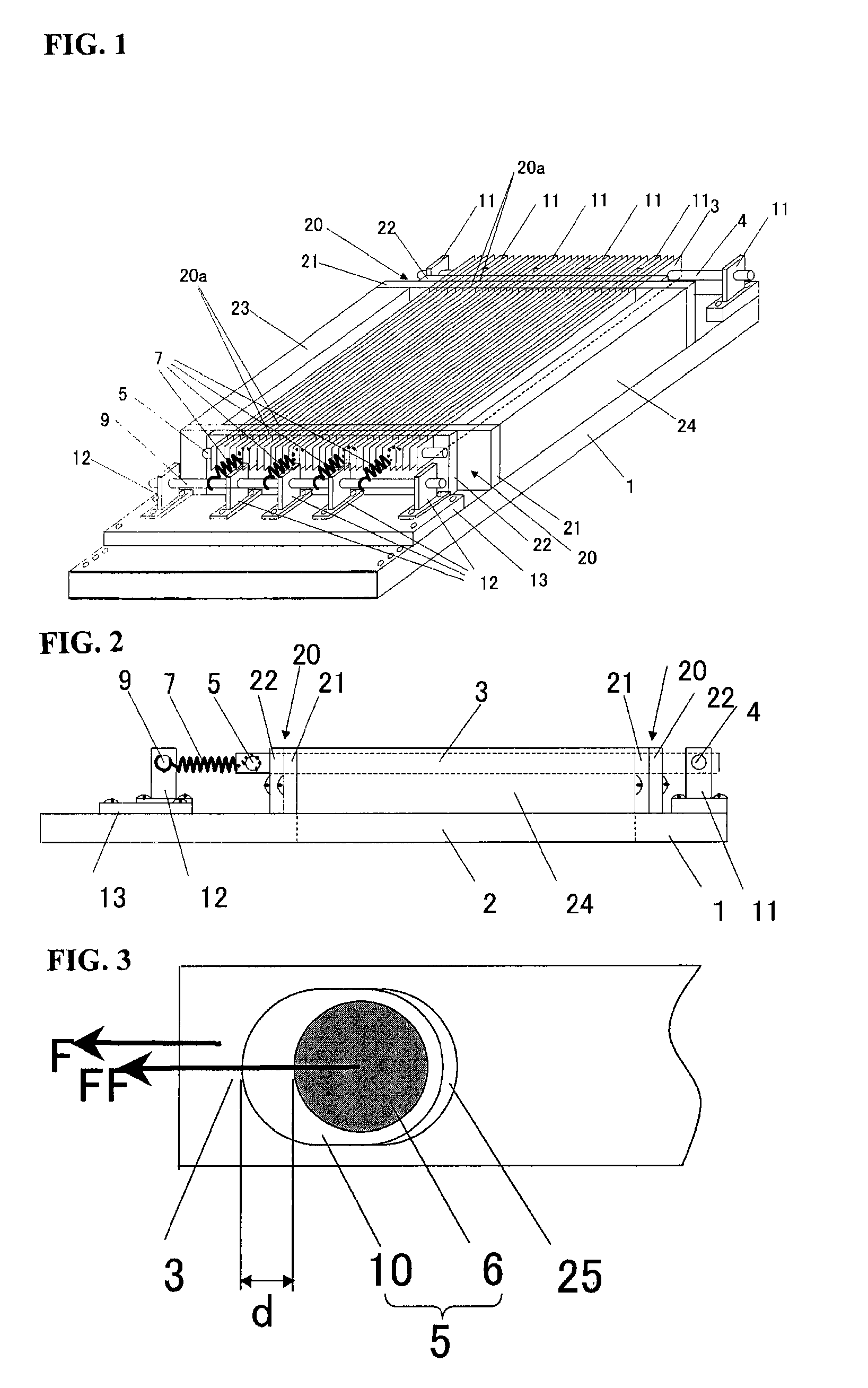
[0021]FIG. 1 is an oblique view used, to show a process of manufacturing a scattered X-ray eliminating grid, and FIG. 2 is a side view thereof.

[0022]Support members 23, 24 are fixed to an upper surface of a rectangular frame 1, which has a slotted space 2, at two sides orthogonal to two opposing sides of the frame 1. In each guide slit mechanism 20, end parts of a guide slit plate 21 are fixed to end parts of the support members 23, 24, and a guide slit plate 22 is fixed, to the guide slit plate 21 such that the guide slit plate 21 and the guide slit plate 22 overlap in the plate thickness directions. The guide slit plate 22 is screwed to the guide slit plate 21 and the screwing through hole has a requisite clearance for that screw; furthermore, within the range of this clearance, the position of the guide slit plate 22 with respect to the guide slit plate 21 can be varied in the width directio...


PUM

PropertyMeasurementUnit
focal lengthaaaaaaaaaa
tensionaaaaaaaaaa
thicknessaaaaaaaaaa

Abstract

Problems SolvedThe information solves the problem of how to provide a structure and a manufacturing method that can inexpensively and stably obtain a scattered X-ray eliminating grid wherein air serves as an intermediate substance even as X-ray absorbing substance parts are accurately positioned and held. SolutionThe invention includes disposing guide slit plate mechanisms fixed relative to one another, namely, parallel to and spaced apart from one another by a prescribed distance; fitting metal foils, which serve as X-ray absorbing substance provided between the guide slit plate mechanisms, parallel to primary X-rays; inserting both ends of the metal foils into the guide slit plate mechanisms; inserting, when applying tension evenly, a rod, which is sheathed in an elastic body, into holes formed in the metal foils on the tip sides of the metal foils beyond the inserted portions; and adopting a structure that ensures that the cross sectional shape of the elastic body sheathing the rod has a sufficient wall thickness in a direction in which the elastic body is compressed when tension is generated, and thereby eliminating any difference in the tension even if a spring constant k that is determined during compression is small and the amounts of compression are different.

Description

CROSS REFERENCE TO RELATED APPLICATIONS[0001]This application is a National Stage application under 35 U.S.C. §371, of International Application PCT / JP2008 / 063127 filed on Jul. 22, 2008, which was published as WO 2010 / 010607 on Jan. 28, 2010. The application is incorporated herein by reference.FIELD OF THE INVENTION[0002]The present invention relates to a method of manufacturing a scattered, radiation eliminating grid, and more particularly relates to a method of manufacturing a scattered radiation eliminating grid wherein air serves as an intermediate substance.BACKGROUND OF THE INVENTION[0003]For example, in an X-ray radiographic apparatus or an X-ray CT apparatus used in medical or industrial settings, a scattered X-ray eliminating grid is generally disposed between a subject and an X-ray detector with the goal of preventing X-rays scattered, by the subject from impinging the X-ray detector.[0004]This type of grid comprises numerous foil shaped. X-ray absorbing substance, which a...

Claims


Application Information

Patent Timeline
Patent Type & Authority Patents(United States)
IPC IPC(8): H01S4/00
CPCG21K1/025Y10T29/49016Y10T29/49826Y10T29/49002
Inventor TONAMI, HIROMICHI
Owner SHIMADZU CORP
Why Eureka
Try Eureka