Fluoroscopic apparatus and method

a fluoroscopic and apparatus technology, applied in the field of fluoroscopic apparatus and method, can solve the problems of over-described conventional apparatus, unvisualized and useless x-ray radiation of subjects, and above-described conventional apparatus has a disadvantage in operability, so as to reduce the exposure dose and simplify the operation.

Inactive Publication Date: 2006-07-11
CANON KK
View PDF5 Cites 7 Cited by
  • Summary
  • Abstract
  • Description
  • Claims
  • Application Information

AI Technical Summary

Benefits of technology

[0014]An object of the present invention is to provide a fluoroscopic apparatus and method which can take a radiograph with a simplified operation and reduces an exposure dose.

Problems solved by technology

However, the above-described conventional apparatus has the problems described below.
But, the above conventional apparatus has a disadvantage in operability.
In addition, a technology is known which synchronizes an irradiated area with X-ray to a visual field size by controlling the opening of the X-ray aperture 2 in accordance with a selected visual field size, when changing the visual field size of the I. I. 3a to a smaller size during fluoroscopy, but according to the technology, the subject is irradiated with unvisualized and useless X-rays while the X-ray aperture 2 is moving.

Method used


Image

  • Fluoroscopic apparatus and method
  • Fluoroscopic apparatus and method
  • Fluoroscopic apparatus and method

Examples


embodiment 1

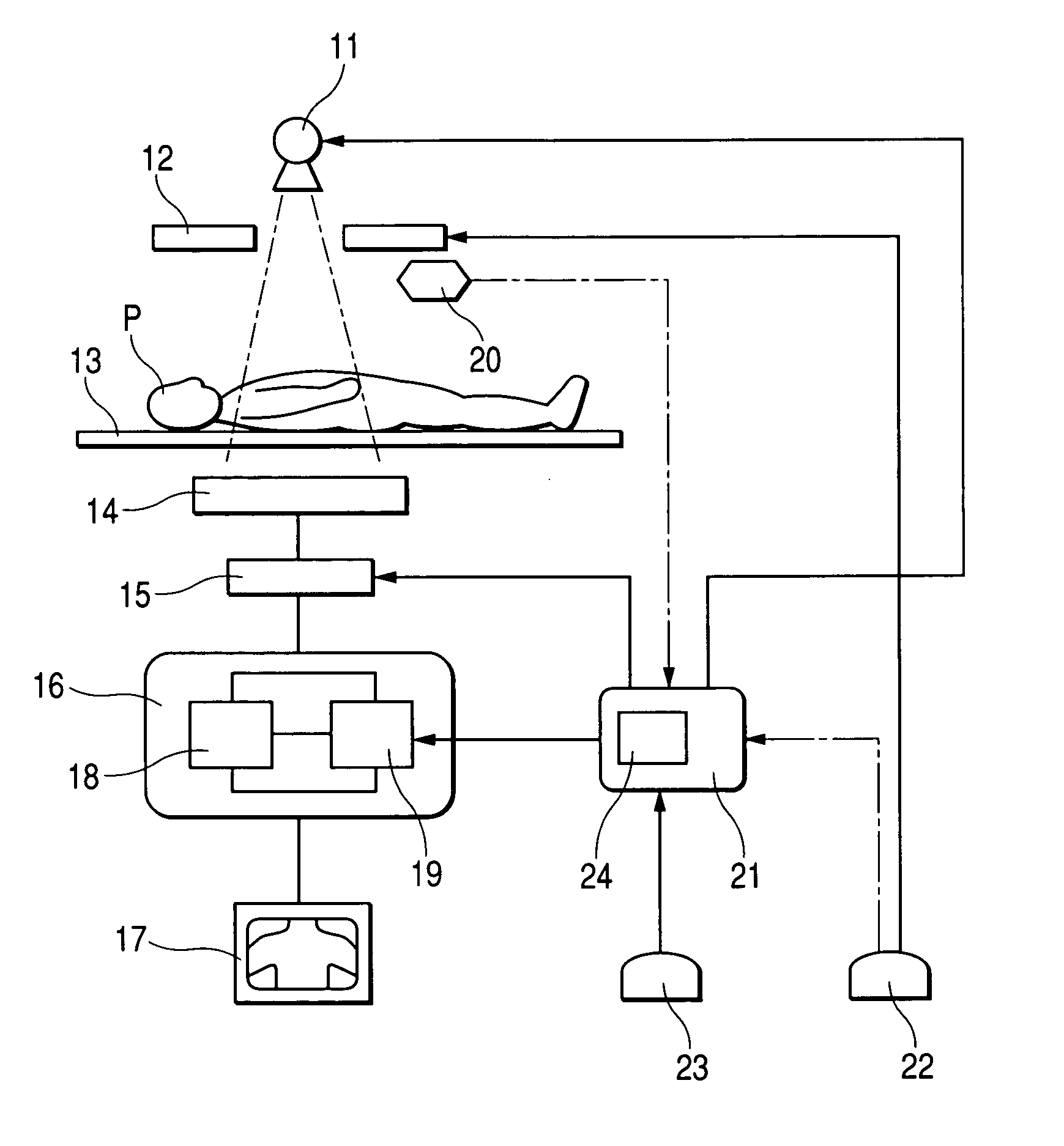
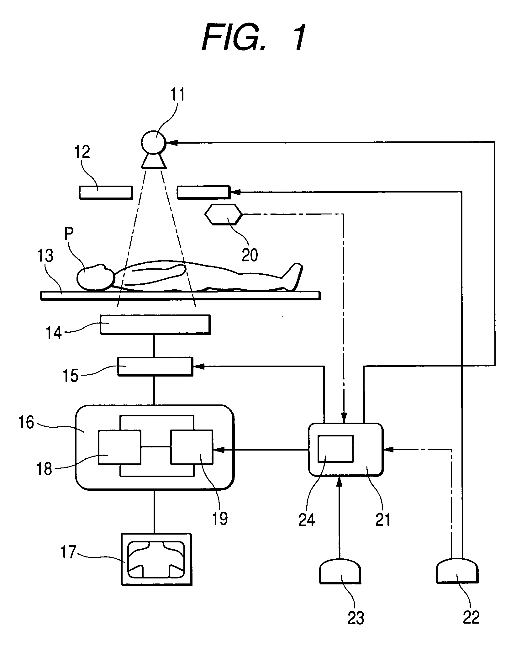
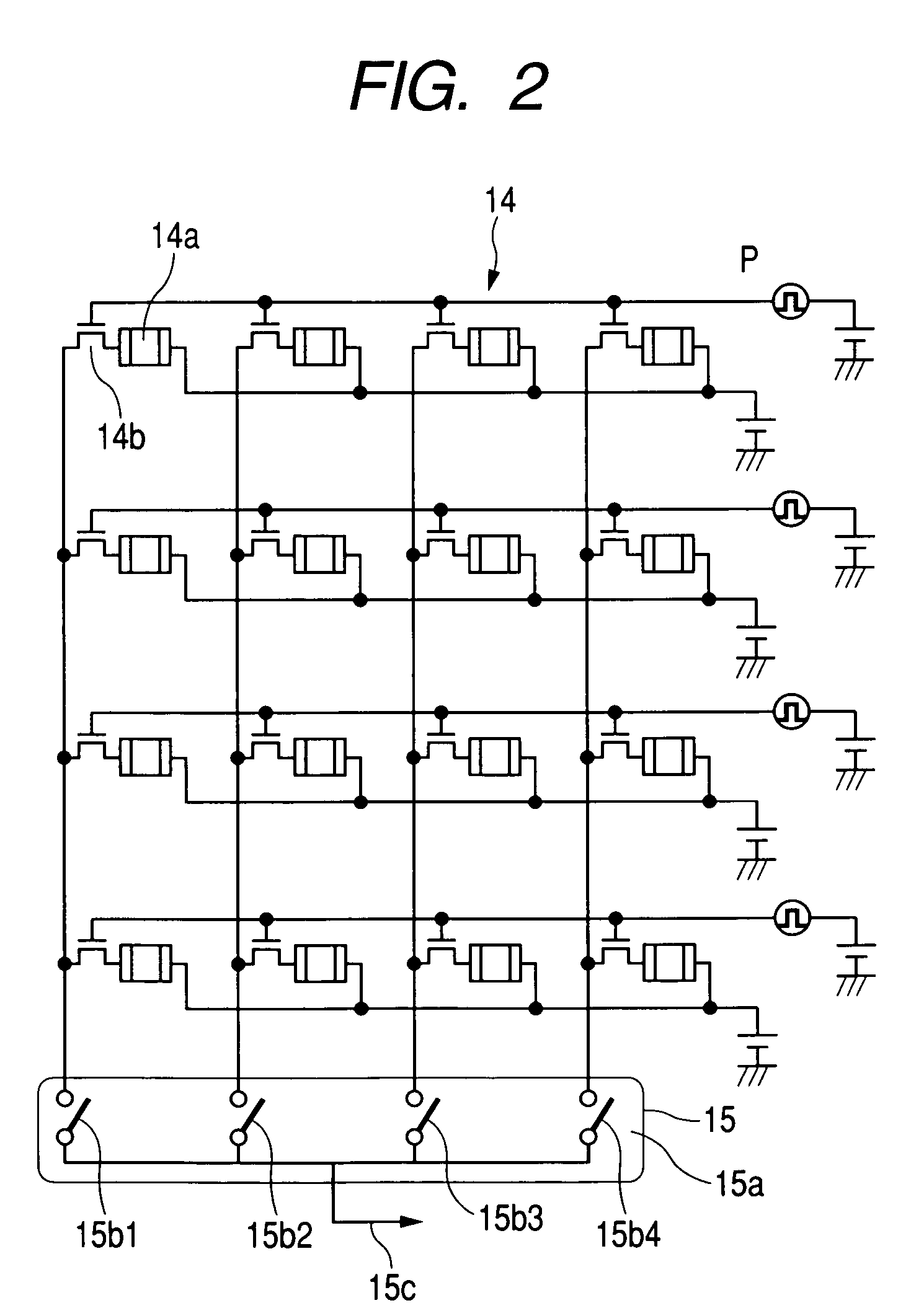
[0032]FIG. 1 is a block diagram showing the embodiment 1 of a fluoroscopic apparatus. The fluoroscopic apparatus has sequentially an X-ray aperture 12 for determining an X-ray radiation field, a top plate 13 for mounting a subject P thereon, and a planar X-ray-detecting element 14 for detecting the X-rays having passed through the subject P, disposed in front of an X-ray tube 11 for irradiating the subject P with X-rays.

[0033]The output of a planar X-ray-detecting element 14 is sequentially connected to a reading circuit 15 for reading picture signals from the planar X-ray-detecting element 14, an image processing part 16 for image-processing read picture signals, and a display 17 such as a television monitor for visualizing the picture signals. The image processing part 16 has a memory 18 for keeping the picture signals and a computing unit 19 installed in the inside.

[0034]In the vicinity of an X-ray aperture 12, opening sensing means 20 for detecting the opening of the X-ray apert...

embodiment 2

[0057]In the embodiment 1, picture signals stored in adjacent transducing elements 14a are added in a reading step, but a picture signal in every transducing element 14a may be individually read and converted to digital picture signals, then the adjacent picture signals may be added in a computing unit 19, and the X-ray pictorial image may be displayed. In addition, if the resolution need not be changed in radiography for each irradiation field R, the correlation table may be set so as to synchronize with only an X-ray tube current (A) in accordance with change of the irradiation field R.

[0058]FIG. 5 is a flow chart of the embodiment 2. Table 2 shows a correlation table between a field size and an X-ray irradiation condition in synchronization with a reading or computing method in the embodiment 2.

[0059]

TABLE 2Reading / IrradiationTube voltageTube currentcomputingfield R(V)(A)methodR ≦ R3V1A3no additionof pixelsR3 V1A2addition of4 pixelsR2 V1A3no additionof pixelsA2addition of4 pixels...

embodiment 3

[0064]Table 3 shows a correlation table between a size of an irradiation field R and a reading or computing method in synchronization with an X-ray irradiation condition in the embodiment 3.

[0065]

TABLE 3Reading / IrradiationTube voltageTube currentcomputingfield R(V)(A)methodR ≦ R3V1A3no additionof pixelsR3 V1A2addition of4 pixelsR2 V1A2 no additionof pixelsA1 addition of4 pixelsA1addition of16 pixels

[0066]In addition, in a block diagram in FIG. 1, the tube current (A) of an X-ray tube 11 can be changed through input means 23 during fluoroscopy of a subject P.

[0067]A radiographic step using a radiographic apparatus having such a configuration is advantageous as follows. In a flow chart shown in FIG. 5, for instance, when an irradiation field R1 is set similarly in the case of the embodiment 1, radiography is started under an irradiation condition of a tube voltage (V) of V1 and a tube current (A) of A1 as a default condition, the X-ray image of the whole chest B is observed, in which ...


PUM


Abstract

The object of the present invention is to enable photographing of a desired X-ray image in accordance with each of fluoroscopy, radiography of moving images in an area of interest and spot radiography by simplified operations, and to reduce an exposure dose to a subject. A correlation table is previously input before radiographing (S1), and is memorized (S2). A radiographer sets an irradiation field R to R1 (S3), and an X-ray aperture is opened by predetermined quantity (S4). An opening value is sent to a control part (S5), and X-rays irradiate a subject P on an irradiation condition of a tube voltage (V) and tube current (A) based on the correlation table (S6). The emitted X-rays pass through the subject, enter a planar X-ray-detecting element, then are read and converted to picture signals. In addition, a method of reading picture signals through a reading circuit can be linked to information on the correlation table, and the reading circuit is controlled so as to add picture signals, for instance, of 4 by 4 (=16) pixels which are adjacent to each other into a picture signal of 1 pixel and read it (S7).

Description

BACKGROUND OF THE INVENTION[0001]1. Field of the Invention[0002]The present invention relates to a fluoroscopic apparatus and method for radiographing an image by using a radioactive ray such as an X-ray.[0003]2. Related Background Art[0004]In the field of diagnostic imaging using a radiographic apparatus, particularly in a fluoroscopic apparatus, an I. I. (an image intensifier)-television system is used widely. More specifically, in the apparatus, as shown in FIG. 6, a subject P is irradiated with X-rays emitted from an X-ray tube 1 through an X-ray aperture 2, the transmitted X-rays which have passed through the subject P, are detected with a detecting unit 3 and are converted to picture signals, and then the converted picture signals are displayed on a monitor 5 as images through image processing means 4.[0005]X-rays to irradiate the subject P, is set so as to irradiate an only the predetermined area required for radiography through the X-ray aperture 2. A detecting unit 3 conver...

Claims


Application Information

Patent Timeline
Patent Type & Authority Patents(United States)
IPC IPC(8): H05G1/26G03B42/02A61B6/00A61B6/06H04N5/321
CPCA61B6/06H04N5/321A61B6/542A61B6/00G03B42/02
Inventor MATSUMOTO, KAZUHIRO
Owner CANON KK
Why Eureka
Try Eureka