Metal plate forming device

A metal plate and metal plate technology, which is applied in the field of metal plate forming devices, can solve problems such as incomplete molding of blanks, poor flow channel size accuracy, and high thinning rate of bipolar plates, so as to avoid spark discharge, The effect of simple structure, low resistance and inductance

Inactive Publication Date: 2012-05-16
METAL INDS RES & DEV CENT
View PDF9 Cites 28 Cited by
  • Summary
  • Abstract
  • Description
  • Claims
  • Application Information

AI Technical Summary

Problems solved by technology

However, the disadvantages of this patented method are: the local thinning rate of the formed bipolar plate is high, and the billet is not completely molded, so the dimensional accuracy of the flow channel is not good

Method used


Image

  • Metal plate forming device
  • Metal plate forming device
  • Metal plate forming device

Examples


Embodiment Construction

[0031] In order to have a clearer understanding of the technical features, objects and effects of the present invention, the specific embodiments of the present invention will now be described with reference to the accompanying drawings.

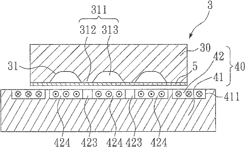
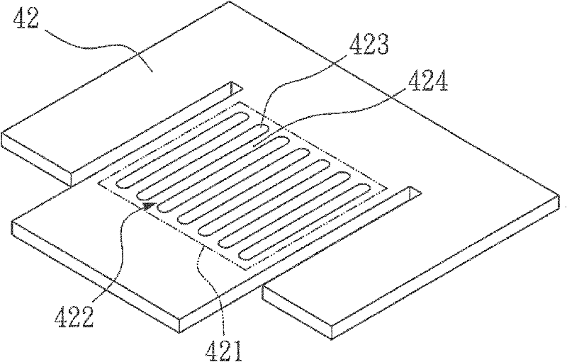
[0032] figure 2 A schematic diagram showing a first embodiment of the sheet metal forming apparatus of the present invention; image 3 A schematic diagram showing a first embodiment of the plate-shaped electromagnetic coil of the present invention. mate reference figure 2 and image 3 , the sheet metal forming device 3 includes a mold 30 and an electromagnetic generating device 40 . The mold 30 has a forming surface 31 , and the forming surface 31 has a pattern structure 311 . The pattern structure 311 includes at least one high portion 312 and at least one low portion 313 . In this embodiment, the pattern structure 311 includes a plurality of high portions (protrusion structures) 312 and a plurality of low portions (groove structures)...


PUM


Abstract

The invention discloses a metal plate forming device which comprises a mold and an electromagnetic production device, wherein a forming mask of the mold has a pattern structure, and the pattern structure comprises at least one high part and at least one low part; a plate-shaped electromagnetic coil of the electromagnetic production device has a forming region, and a feature structure corresponding to the pattern structure is arranged in the forming region; and a metal plate can be driven by a mutually-repelled electromagnetic force generated between the plate-shaped electromagnetic coil and the metal plate to abut on the pattern structure, thereby forming the preset pattern. Thus, the metal plate forming device has the following advantages: the lateral binding force of the blank (metal plate) in the forming process can be reduced; the formed pattern has a higher depth-width ratio; the forming performance of the blank is improved; the thinning rate and warpage problem of the blank can be reduced; the structure is simple; a higher primary current value can be produced; and the arcing discharge problem can be completely avoided.

Description

technical field [0001] The present invention relates to a forming device, especially a metal sheet forming device. Background technique [0002] refer to figure 1 , which shows a schematic diagram of the prior art forming a sheet metal part. In the prior art, a uniform electromagnetic force F1 is used to drive a metal plate 1 to impact a forming surface of a mold 2 , wherein the forming surface has a plurality of convex portions 21 and a plurality of concave portions 22 . During the forming process, the metal plate 1 will first contact the convex portion 21 , and the convex portion 21 will generate a reaction force F2 of the same magnitude, and then part of the metal plate 1 will deform and extend to the concave portion 22 . However, because all areas of the metal plate 1 are subjected to the uniform electromagnetic force F1, some of the metal plate 1 will be subjected to the electromagnetic force F1 and the reaction force F2 at the position of the convex portion 21 when e...

Claims


Application Information

Patent Timeline
Patent Type & Authority Applications(China)
IPC IPC(8): B21D26/14
Inventor 郑东辰张灿勋王俊杰苏子可
Owner METAL INDS RES & DEV CENT
Why Eureka
Try Eureka