Precast slab construction member

A technology of prefabricated panels and components, applied in building components, floor slabs, building structures, etc., can solve the problems of troublesome structural connection, poor integrity, and cumbersome components, saving materials and labor, easy transportation and installation, and high overall strength. Effect

Inactive Publication Date: 2012-05-16
CHINA METALLURGICAL CONSTR ENG GRP
View PDF8 Cites 9 Cited by
  • Summary
  • Abstract
  • Description
  • Claims
  • Application Information

AI Technical Summary

Problems solved by technology

At present, there are many ways to construct the floor slabs of high-rise buildings. One way is to pour concrete on site. Wiring pipes, steel bars on the upper part of the binding plate, inspection and acceptance, and concrete pouring. Among them, the bottom formwork of the support plate is a large amount of work, which requires a lot of formwork and labor, and the construction procedures and management are complicated, and the construction cost is high.
Another method is to use factory prefabricated concrete structural components, assemble them on site and cast in-situ joints. Although this method is fast, the components are heavy, hoisting and transportation are very inconvenient, and the structure and connection are troublesome.
Chinese utility model patent CN2407059Y discloses a prestressed and non-prestressed laminated slab, which is composed of prefabricated laminated slabs and laminated layers. , The relationship between the laminated slab and the laminated layer is only laminated, no concrete is poured, the integrity is poor, and the seismic performance is poor
Chinese invention patent CN102011446A discloses a semi-prefabricated floor slab component used in the construction method without on-site formwork. The floor slab component includes main reinforcement, reinforcement and corrugated reinforcement. The transverse main reinforcement is welded with multiple longitudinal reinforcements passing in parallel. The lower half wave of the corrugated reinforcement is buried in the concrete layer, and the upper half wave is exposed outside the concrete layer. The floor components are prefabricated by the prefabrication factory and hoisted to the building frame After being installed, continue to bind the main reinforcement and reinforcement in the compression area of ​​the floor slab, and then pour the upper part of the floor. On-site binding does not realize that the components are completely prefabricated by the prefabrication factory to achieve industrial production, and only the corrugated bars are provided on the horizontal main bars, and there are no corrugated bars on the longitudinal main bars, which cannot play a good supporting role in the layout of the steel bars in the compression zone

Method used


Image

  • Precast slab construction member
  • Precast slab construction member
  • Precast slab construction member

Examples


Embodiment 1

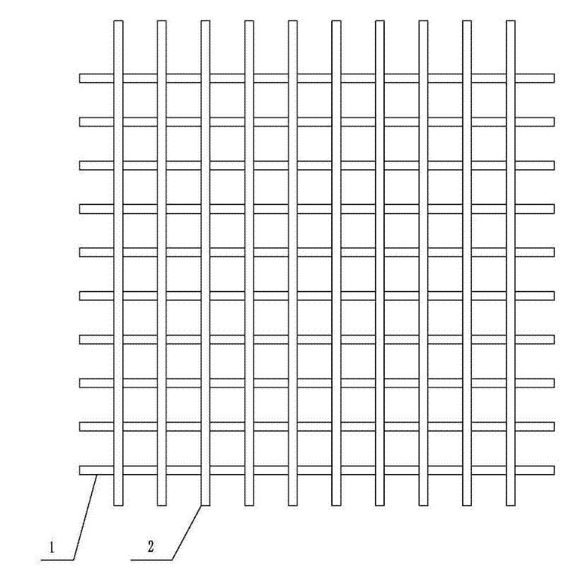
[0029] like figure 1 , figure 2 and image 3 As shown, a prefabricated slab construction component includes an upper layer of steel mesh and a lower layer of steel mesh. Both the upper and lower layers of steel mesh are composed of transverse bars 1 and longitudinal bars 2. Both the transverse bars 1 and the longitudinal bars 2 are HRB500 hot-rolled ribbed bars. The diameter 15mm, the yield strength is not less than 500Mpa, the horizontal reinforcement 1 is arranged in parallel first, and then the longitudinal reinforcement 2 is arranged in parallel, so that the horizontal reinforcement 1 and the longitudinal reinforcement 2 intersect, the angle at the intersection is 90 degrees, and the intersection is fixed by welding, or the longitudinal reinforcement 2 is arranged first , and then lay out the transverse bar 1, the upper and lower steel meshes are laid out in the same way to form the same mesh surface, and then the lower layer of steel mesh is selected as the bottom surfa...

Embodiment 2

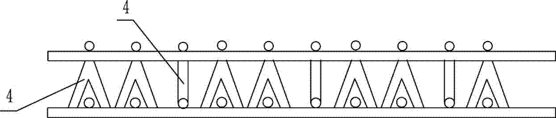
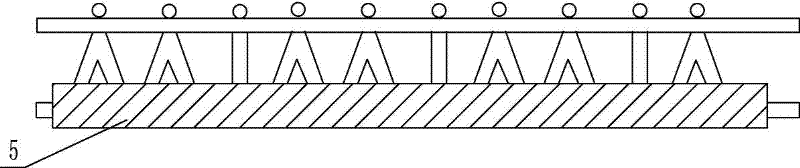
[0031] like Figure 4 , Figure 5 , Figure 6 and Figure 7 As shown, select steel bars of the same material as in Example 1, and use the same method to lay out transverse bars 1 and longitudinal bars 2, because the upper area of ​​the floor is the compression area, and the lower area is the tension area, and the compression area is subject to greater pressure and less tension. , so the density of the upper layer of reinforcement mesh should be smaller than that of the lower layer of reinforcement mesh, and the spacing of the upper layer of reinforcement mesh is four times that of the lower layer of reinforcement mesh. The shear stud 3 is welded into a V-shape by two steel bars, and one end of the two steel bars is welded together to form the top of the shear stud 3, and the two points at the bottom are welded to a horizontal bar 1 or a longitudinal bar 2 of the lower steel mesh, The top of the shear stud 3 is welded and fixed to the upper layer of steel mesh. In order to m...


PUM


Abstract

The invention relates to a precast slab construction member, which belongs to the field of building members. The precast slab construction member comprises an upper layer reinforcing mesh and a lower layer reinforcing mesh, wherein both the upper layer reinforcing mesh and the lower layer reinforcing mesh comprise transverse bars and longitudinal bars which are arranged parallelly at intervals and are intersected and welded at intersection points; shear nails are welded between the upper layer reinforcing mesh and the lower layer reinforcing mesh; and the lower layer reinforcing mesh is buried into concrete. Due to the precast slab construction member, a bottom slab die is not needed to be supported, reinforcing bars of a floor are fully precast into a whole body by a precasting factory, the production and mounting rates are high, and the overall intensity is high, and thus the problems that the bottom slab die is needed to be supported, the reinforcing bars of the floor are bound on site, and the construction rate is low in the prior art are solved.

Description

[0001] technical field [0002] The invention relates to a building component, in particular to a prefabricated panel construction component. [0003] Background technique [0004] The upper half of the floor of a high-rise building is mainly under pressure, called the compression zone, and the lower half of the floor is mainly under tension, called the tension zone. At present, there are many ways to construct the floor slabs of high-rise buildings. One way is to pour concrete on site. The wiring pipes, the upper reinforcement of the binding plate, the inspection and acceptance, and the concrete pouring, among them, the bottom formwork of the support plate is a large amount of work, which requires a lot of formwork and labor, and the construction procedures and management are complicated, and the construction cost is high. Another method is to use factory prefabricated concrete structural components, assemble them on site and cast in-situ joints. Although this method ...

Claims


Application Information

Patent Timeline
Patent Type & Authority Applications(China)
IPC IPC(8): E04B5/17
Inventor 李智能
Owner CHINA METALLURGICAL CONSTR ENG GRP
Why Eureka
Try Eureka