
Projection system

A projection system and projector technology, applied in the field of projection, can solve the problems affecting the viewing comfort of the observer, the discomfort of the observer's eyes, etc., and achieve the effects of improving viewing comfort, simple structure, and easy implementation.

Active Publication Date: 2012-05-16
KUSN INFOVISION OPTOELECTRONICS
View PDF5 Cites 6 Cited by
  • Summary
  • Abstract
  • Description
  • Claims
  • Application Information

AI Technical Summary

Problems solved by technology

However, this image projection method requires the observer to wear matching polarizers to watch the projected three-dimensional image when viewing, which will cause discomfort to the observer's eyes and affect the viewing comfort of the observer.

Method used


Image

  • Projection system
  • Projection system
  • Projection system

Examples


Embodiment Construction

[0014] In order to make the above objects, features and advantages of the present invention more comprehensible, specific implementations of the present invention will be described in detail below in conjunction with the accompanying drawings.

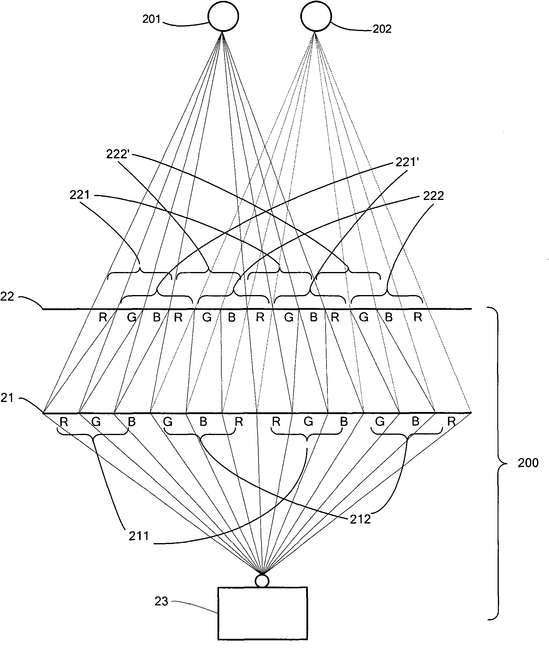
[0015] figure 2 It is a schematic diagram of a projection system according to an embodiment of the present invention. Such as figure 2 As shown, the projection system 200 of the present invention includes a first screen 21, a second screen 22 positioned in front of the first screen 21, a projector 23 positioned behind the first screen 21, and an image generating device electrically connected to the projector 23 (not shown), wherein, the first screen 21 and the second screen 22 are transmission screens, and the projector 23 is a rear projector. The first screen 21 and the second screen 22 are placed parallel to each other, and a predetermined distance is kept between the first screen 21 and the second screen 22. In one embodiment, t...


PUM


Abstract

The invention discloses a projection system, comprising a projector, a first screen and a second screen, wherein the first screen comprises a plurality of first regions and a plurality of second regions; image light beams are projected to the first screen by the projector; the image light beams which penetrate through the first regions can penetrate through the second screen to enter into the right eye of an observer at a pre-set position, but cannot penetrate through the second screen to enter into the left eye of the observer; the image light beams which penetrate through the second regions can penetrate through the second screen to enter into the left eye of the observer, but cannot penetrate through the second screen to enter into the right eye of the observer. Therefore, the projection display of three-dimensional images is realized and the observer can see the three-dimensional images by naked eyes.

Description

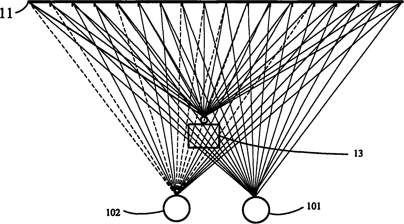
technical field [0001] The invention relates to the technical field of projection, in particular to a projection system for stereoscopic display. Background technique [0002] In general, a projector has a function of easily enlarging the screen size according to its projection distance, and therefore, it is possible to easily realize image display on a large screen. The projector includes a front projector and a rear projector. The front projector projects and displays images on a reflective screen, while the rear projector projects and displays images on a transmissive screen. figure 1 A schematic diagram of an existing projection display system is disclosed. Such as figure 1 As shown, the projection display system includes a reflective screen 11 and a front projector 13 located in front of the reflective screen 11 . The projector 13 includes a light source, an imaging assembly, a filter assembly, and a projection lens, etc., wherein the filter assembly includes a plura...

Claims


Application Information

Patent Timeline
Patent Type & Authority Applications(China)
IPC IPC(8): G02B27/22G03B21/56G03B21/00H04N13/00
Inventor 宋善专司秉玉
Owner KUSN INFOVISION OPTOELECTRONICS
Learn More