Object inspection systems and methods

A technology for inspection systems and objects, applied in the field of object inspection systems in the field of lithography technology, and can solve problems such as inability to provide detection sensitivity

Inactive Publication Date: 2012-05-16
ASML NETHERLANDS BV +1
View PDF8 Cites 17 Cited by
  • Summary
  • Abstract
  • Description
  • Claims
  • Application Information

AI Technical Summary

Problems solved by technology

Scanning imaging systems, such as Critical Dimension Scanning Electron Microscopy (CDSEM), can be sensitive to small defects (such as defects with feature siz...

Method used


Image

  • Object inspection systems and methods
  • Object inspection systems and methods
  • Object inspection systems and methods

Examples


Embodiment Construction

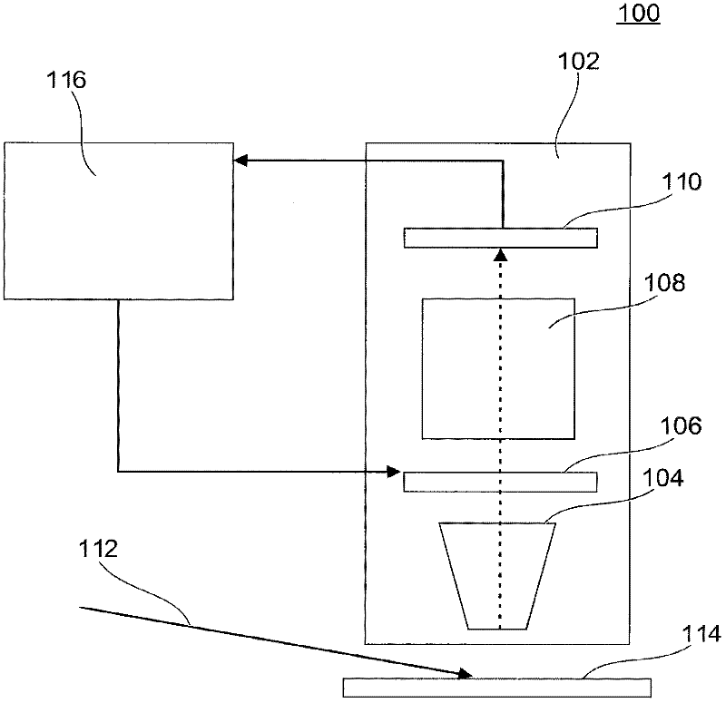
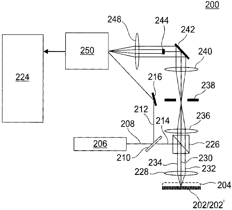
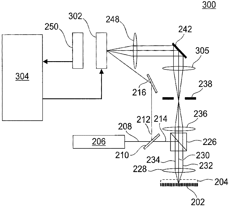
[0035] Embodiments of the invention relate to object inspection systems and methods. This specification discloses one or more embodiments that incorporate the features of this invention. The disclosed embodiments are merely exemplary of the invention. The scope of the present invention is not limited to these disclosed embodiments. The invention is defined by the appended claims.

[0036] The described embodiments and references in the specification to "one embodiment," "an embodiment," "exemplary embodiment," etc. mean that the described embodiments may include particular features, structures, or characteristics, but each embodiment It may not be necessary to include specific features, structures or characteristics. Also, these paragraphs are not necessarily referring to the same embodiment. Furthermore, when particular features, structures or characteristics are described in conjunction with an embodiment, it should be understood that it is within the scope of knowledge ...


PUM


Abstract

Disclosed are systems and methods for object inspection, in particular for inspection of reticles used in a lithography process. The method includes interferometrically combining a reference radiation beam with a probe radiation beam, and storing their complex field images. The complex field image of one object is then compared with that of a reference object to determine the differences. The systems and methods have particular utility in the inspection of a reticle for defects.

Description

[0001] Cross References to Related Applications [0002] This application claims the benefit of priority to US Provisional Application 61 / 219,158, filed June 22, 2009, which is hereby incorporated by reference in its entirety. technical field [0003] Embodiments of the invention relate generally to object inspection systems and methods, and in particular to object inspection systems and methods in the field of lithography, where the object to be inspected may be, for example, a reticle or other patterning device. Background technique [0004] Photolithography is widely recognized as one of the key steps in the fabrication of integrated circuits (ICs) and other devices and / or structures. However, as the dimensions of features formed using lithography become smaller and smaller, lithography is becoming a more critical factor for achieving miniature ICs or other devices and / or structures to be fabricated. [0005] A lithographic apparatus is a machine that applies a desired p...

Claims


Application Information

Patent Timeline
IPC IPC(8): G01N21/94G01N21/956
CPCG03F1/84G01N2021/95676G01N21/95607G01N21/94G03H2001/0447G03H2001/0264G03H2223/12G03H1/0443G03H2222/43G03H2223/55G03H2001/0456G03H2001/0458
Inventor A·邓鲍夫Y·乌拉迪米尔斯基Y·沙玛莱L·斯卡克卡巴拉兹R·萨拉尔德森R·雅各布斯
Owner ASML NETHERLANDS BV
Why Eureka
Try Eureka