Compression device and operation control method thereof

A compression device, operation control technology, applied in the direction of pump control, liquid variable capacity machinery, machine/engine, etc., can solve the switching of compressor start and stop, frequent switching of loading and unloading, prone to abnormalities or failures, control Frequency increase and other problems, to achieve the effect of saving power consumption, saving power consumption, and reducing control frequency

Inactive Publication Date: 2015-09-09
ANEST IWATA CORP
View PDF12 Cites 2 Cited by
  • Summary
  • Abstract
  • Description
  • Claims
  • Application Information

AI Technical Summary

Problems solved by technology

Therefore, there is a problem that failure of the compressor or burnout of the motor is likely to occur
In addition, the control frequency of the control system increases, so that abnormalities or malfunctions are prone to occur
[0011] In addition, in the operation control method disclosed in Patent Document 2 or Patent Document 3, the amount of change in the discharge flow rate or discharge pressure of compressed air is obtained per unit time, and the number of operating compressors is changed according to the change amount. For pressure control with good precision, the shorter the unit time, the more frequent the switching between starting and stopping of the compressor, or switching between loading and unloading, and the same problem as in Patent Document 1 arises.

Method used


Image

  • Compression device and operation control method thereof
  • Compression device and operation control method thereof
  • Compression device and operation control method thereof

Examples


Embodiment approach 1

[0048] based on Figure 6 ~ Figure 10 The first embodiment of the method and device of the present invention will be described. exist Figure 6 Among them, the compression device 10 includes four air compressors 12a to 12d. The electromagnetic switch 16a-d which switches and controls each motor 14a-d of the air compressors 12a-d is provided as an unloading mechanism which makes the air compressors 12a-d into an unloaded state. However, the unloading mechanism is not limited to this.

[0049] In addition, examples of the unloading mechanism include (1) a mechanism using an intake valve, (2) a mechanism using a vent valve, and the like. Specifically, (1) the mechanism using the suction valve is to continue driving the compressor as it is, and to make the suction valve variable to reduce the suction volume of the compressor to perform no-load operation. This method is mainly applicable to screw compressors. In addition, another mechanism using the suction valve is to continu...

Embodiment approach 2

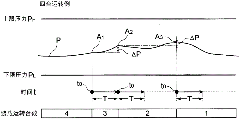
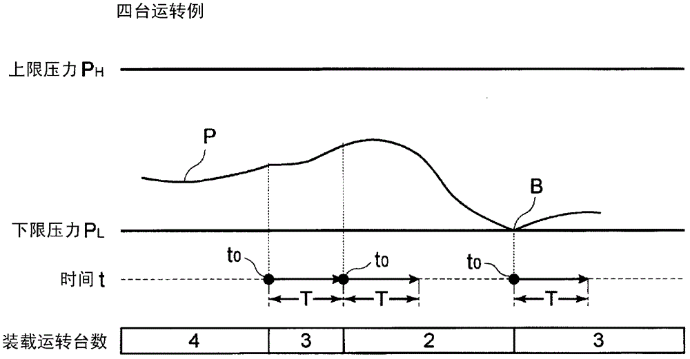
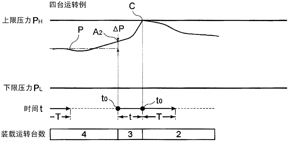
[0075] Next, as a second embodiment, according to Figure 11 Another pressure control example of the operation control of the compression device 10 will be described. Figure 11 It is an example of pressure control from the middle of operation. In the figure, when the ejected air pressure P drops to the lower limit pressure P every time in the low-pressure area L , load switching control is performed. In the medium pressure domain, after the number of operating compressors is changed, the starting point t 0 After the control time T, when the distance from the starting point t 0 The pressure change ΔP is the set increase ΔP S In the above case, unload switching control is performed.

[0076] During unloading promote pressure P P and upper limit pressure P H In the high-pressure domain between, the starting point t after the change of the operating number of the compressor is taken as the starting point t 0 After the control time T, when the ejection pressure P is the un...


PUM


Abstract

The invention provides a compression device and an operation control method thereof. A control time T is set according to service lifetimes of the air compressors (12a-d) and surrounding devices. And the time when the number of the air compressor changes is taken as a start point t0 of the control time T. After the control time I passes and when a pressure changing volume Delta P of the injected compressed air achieves or surpasses a predetermined increase volume Delta PS, a controller (30) controls an electromagnetic shutter (16a-d) to switch one of the compressors from a loading state to an unloading state.

Description

technical field [0001] The present invention relates to a compression device and an operation control method thereof. A plurality of compressors are used to produce compressed gas, and the number of operating compressors is adjusted according to the consumption of the compressed gas, while ensuring the necessary pressure and flow of the compressed gas. Background technique [0002] In factories and the like, a gas compression device is provided in order to supply compressed gas such as compressed air to required posts. In such a gas compression device, the required discharge pressure is secured and the flow rate of the compressed gas is secured. As a gas compression device, a gas compression device is known in which a plurality of compressors are arranged in parallel, and a discharge pipe of each compressor is connected to a compressed air storage tank via a collective pipe. [0003] In this gas compression device, a pressure sensor is provided on a compressed air storage t...

Claims


Application Information

Patent Timeline
Patent Type & Authority Patents(China)
IPC IPC(8): F04B49/06
Inventor 佐藤和昭
Owner ANEST IWATA CORP
Why Eureka
Try Eureka