
Method and device for controlling real-time dynamic temperatures of machine room and base station

A real-time dynamic and temperature control technology, applied in heating and ventilation control systems, heating methods, household heating, etc., can solve the problems of not considering the energy efficiency ratio of the ventilation system and air conditioning system, single control method, etc., to achieve easy maintenance, The control process is simple and the control process is effective

Inactive Publication Date: 2012-05-23
秦金红
View PDF5 Cites 22 Cited by
  • Summary
  • Abstract
  • Description
  • Claims
  • Application Information

AI Technical Summary

Problems solved by technology

Generally speaking, this solution is still a static temperature control method. By setting the critical temperature to adjust the work of the ventilation fan and air conditioner, it is more energy-efficient than the previous constant temperature air conditioner to control the room temperature. However, the control method is single, and there is still room for further energy saving.
[0006] Another example is the Chinese Patent Application Publication Document with the publication number CN101576306A, which discloses an intelligent temperature control and energy saving method for network communication equipment rooms, and discloses a scheme of using indoor and outdoor heat exchange to achieve temperature control, but there are defects in this scheme. One is the logical starting point for starting the system It is the outdoor temperature, and the outdoor temperature is compared with the set temperature to determine whether to start the ventilator system or the air conditioner system. For the system that controls the room temperature, it is obviously flawed to use this logical starting point; another point, there is no Considering the energy efficiency ratio of ventilation system and air conditioning system, there is room for further improvement of energy saving efficiency

Method used


Image

  • Method and device for controlling real-time dynamic temperatures of machine room and base station
  • Method and device for controlling real-time dynamic temperatures of machine room and base station
  • Method and device for controlling real-time dynamic temperatures of machine room and base station

Examples


Embodiment Construction

[0034] The present invention will be further described below in conjunction with drawings and embodiments.

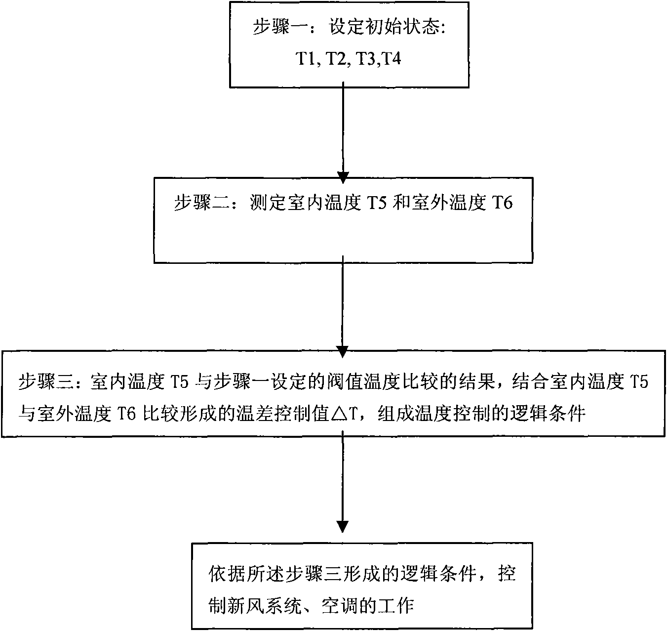
[0035] refer to figure 1 Main realization process flow chart of the present invention. Utilize the process of the inventive method to realize temperature control as follows:

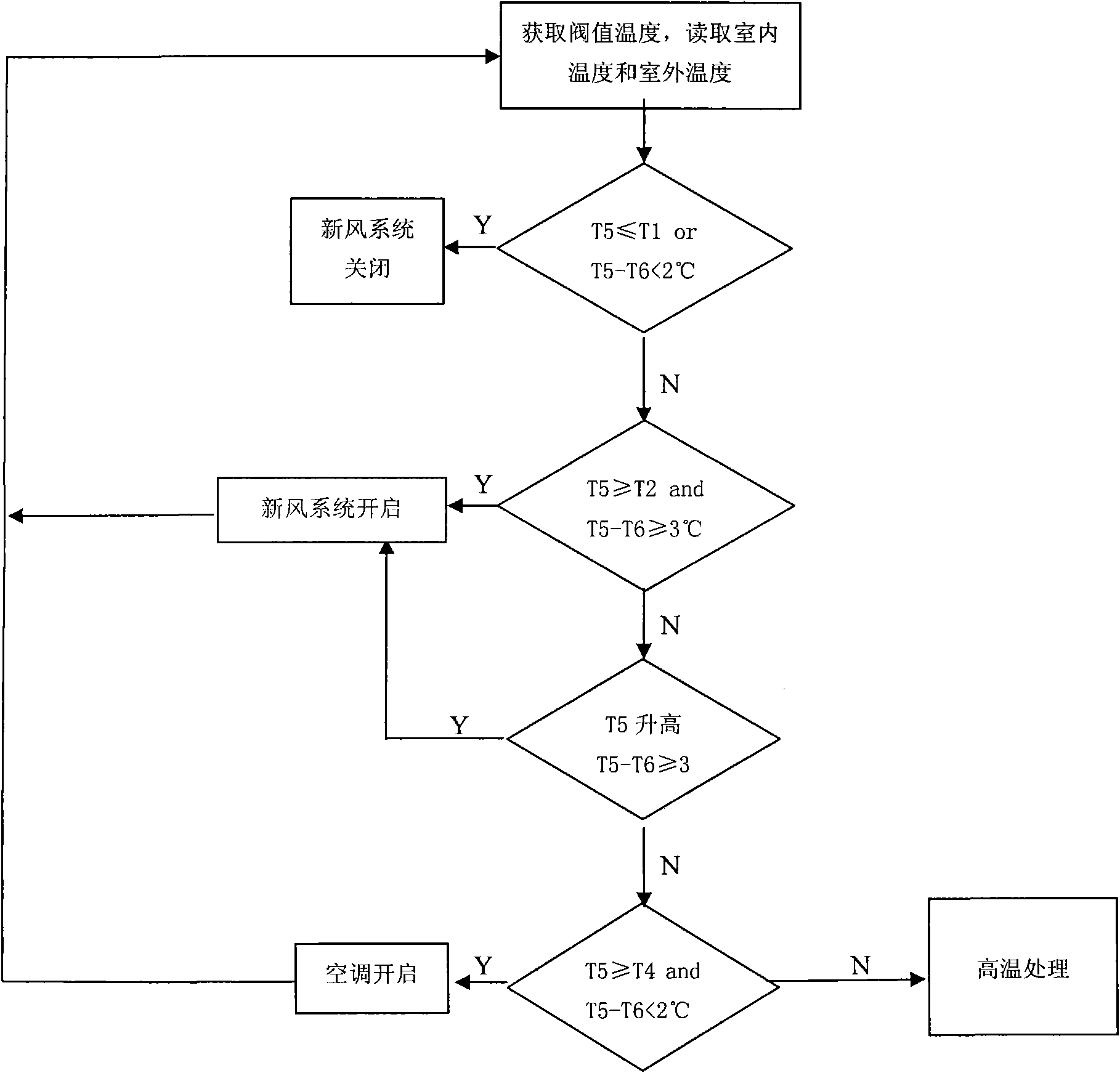
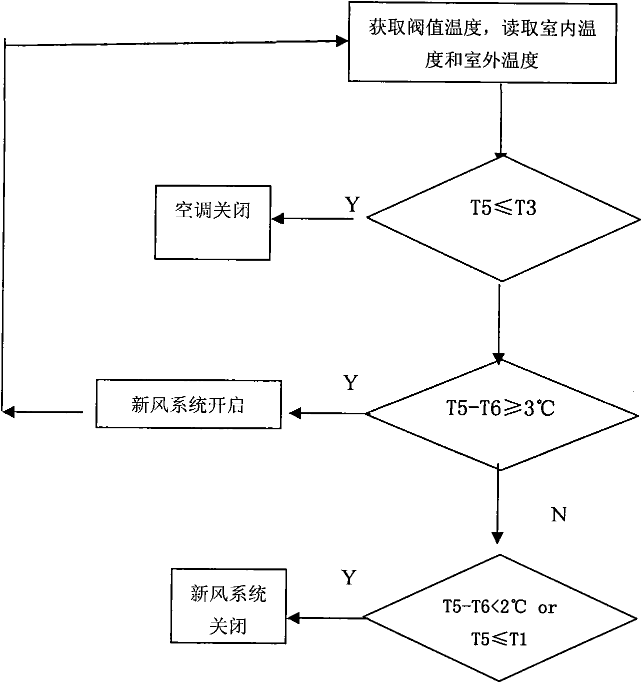
[0036] Step 1: The management personnel set the threshold temperature for the air conditioner and the fresh air system according to the local climate characteristics and indoor temperature requirements: the fresh air system closing temperature T1 (default setting 26°C), the fresh air system opening threshold temperature T2 (default setting 28°C), air conditioner off threshold temperature T3 (default setting 33°C), and air conditioner opening threshold temperature T4 (default setting 35°C).

[0037] In step 2, the indoor temperature T5 and the outdoor temperature T6 are dynamically acquired in real time through the temperature measurement unit.

[0038] Step 3, the result of comparing the indoor...


PUM


Abstract

The invention aims to provide a method and device for controlling real-time dynamic temperatures of a machine room and a base station. The energy-saving effect of energy-saving equipment is increased by improving the temperature control mode. With the help of a fresh air system, based on the auxiliary action of an air conditioner, the method is used for controlling the room temperatures of the machine room and the base station by utilizing the difference of indoor and outdoor temperatures, thus, the purposes of assuring the operation stability and the service life of network equipment and increasing an energy-saving space are achieved.

Description

technical field [0001] The invention relates to a technology for controlling indoor temperature, in particular to a method and device for real-time dynamic temperature control of a computer room and a base station. Background technique [0002] At present, the communication room in my country generally adopts the method of statically increasing the working environment temperature of the equipment to reduce the running time of the air conditioner to achieve energy saving. However, there are many problems in the method of statically increasing the working environment temperature of the equipment. If it is necessary to increase the temperature of the computer room under the premise of ensuring the life of the communication equipment and ensuring the normal operation of the equipment and the network, the increase range is limited and the energy saving space is very small; if the temperature of the computer room is greatly increased to make the equipment work in a high temperatur...

Claims


Application Information

Patent Timeline
IPC IPC(8): F24F11/00F24F11/02
Inventor 秦金红
Owner 秦金红
Learn More