
Integrated circuit for emulating resistor

A technology of integrated circuits and simulated resistors, applied in impedance converters, electrical components, impedance matching networks, etc., and can solve problems such as nonlinear current-voltage characteristics and changes

Inactive Publication Date: 2012-05-23
NXP BV
View PDF4 Cites 3 Cited by
  • Summary
  • Abstract
  • Description
  • Claims
  • Application Information

AI Technical Summary

Problems solved by technology

However, the on-resistance of a MOS transistor with a fixed gate-source voltage Vgs varies with the drain-source voltage Vds, resulting in a non-linear current-voltage characteristic

Method used


Image

  • Integrated circuit for emulating resistor
  • Integrated circuit for emulating resistor
  • Integrated circuit for emulating resistor

Examples


Embodiment Construction

[0066] The present invention provides an integrated circuit for simulating a resistor based on the drain-source resistance of a transistor. The transistor is biased to operate in its linear region and a voltage dependent on the AC source-drain voltage is added to the gate voltage, thereby improving the linearity of the drain-source resistance with respect to the drain-source voltage Spend. Modifications to the gate voltage can be used to alter the transfer function such that the first order part of the dependence of the drain-source resistance on the drain-source voltage is substantially removed.

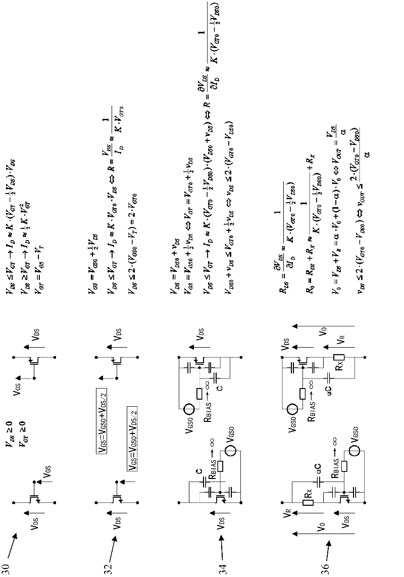
[0067] Figure 3a It is shown step-by-step how to linearize the resistance of a MOS transistor by superimposing a portion of the signal voltage at its drain to its gate. The equations relate to ideal square-law MOS characteristics.

[0068] Figure 3a Analysis of both NMOS and PMOS structures is shown. for equal to V GSO +v DS / 2V GS , the on-resistance of the MOS transistor...


PUM


Abstract

An integrated circuit for emulating a resistor is based on the output resistance of a non-linear circuit element, such as a transistor. In the case of a transistor, it is biased into operation in its linear region, and a voltage dependent on the ac source-drain voltage is coupled to the gate voltage, thereby to improve linearity of the drain-source resistance with respect to the drain-source voltage. This modification to the gate voltage can be used to alter the transfer function such that the drain-source resistance is no longer dependent on the drain-source voltage.

Description

technical field [0001] The invention relates to integrated circuits for simulating resistors. Background technique [0002] Some applications require the use of resistors with good absolute resistance accuracy. The types of resistors available in semiconductor processes for making integrated circuits have limited absolute accuracy due to process variations. Resistor values ​​in a typical semiconductor process are generally considered to be parasitic effects that benefit analog design, and are usually not the main direction of optimization in the process. [0003] Therefore, the resistance variation of a resistor with a given geometry can be large and easily introduce + / - 10-30% uncertainty in absolute value. [0004] In cases where the accuracy of the absolute value of the resistor is important, such as in a characteristic line termination, it is necessary to have the ability to adjust the resistance to the desired value. One known method of resistance adjustment is to us...

Claims


Application Information

Patent Timeline
Patent Type & Authority Applications(China)
IPC IPC(8): H03H11/28H03H11/40
CPCH04L25/0298
Inventor 赫里特·威廉·登贝斯特
Owner NXP BV
Learn More