Power control device

A power control device and controller technology, applied in the field of power supply, can solve the problems of simultaneous conduction of the upper and lower MOS tubes, high process difficulty, and slow response speed, etc., and achieve the effects of smooth start, simple circuit process, and fast response speed

Inactive Publication Date: 2009-10-07
SHENZHEN TCL NEW-TECH CO LTD
View PDF0 Cites 2 Cited by
  • Summary
  • Abstract
  • Description
  • Claims
  • Application Information

AI Technical Summary

Problems solved by technology

[0006] The purpose of the embodiment of the present invention is to provide a power control device, aiming to solve the problem of low reliability, slow response speed, high process difficulty, high cost, hard turn-on of MOS tubes and simultaneous upper and lower MOS tubes in existing LLC power control devices. Conduction problem

Method used


Image

  • Power control device
  • Power control device
  • Power control device

Examples


Embodiment Construction

[0023] In order to make the object, technical solution and advantages of the present invention clearer, the present invention will be further described in detail below in conjunction with the accompanying drawings and embodiments. It should be understood that the specific embodiments described here are only used to explain the present invention, not to limit the present invention.

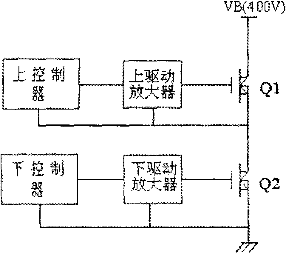
[0024] see figure 2 , is a structural diagram of a power control device according to an embodiment of the present invention. The power control device according to an embodiment of the present invention includes an upper controller, a lower controller, an upper drive amplifier, and a lower drive amplifier. The upper and lower controllers are respectively driven by the upper and lower After the amplifier is driven, it controls the upper switch MOS transistor Q1 and the lower switch MOS transistor Q2 that make up the half bridge. The upper controller and the lower controller are independent and isola...


PUM


Abstract

The invention provides a power control device which comprises an upper controller and a lower controller, wherein the upper controller controls an upper switch MOS tube, the lower controller controls a lower switch MOS tube, and the upper controller and the lower controller are mutually separated and isolated in different planes. The power control device has the advantages of high reliability and reaction speed, simple circuit technology and low manufacturing cost, and can effectively limit various overshoot phenomena.

Description

technical field [0001] The invention belongs to the technical field of power supplies, and in particular relates to a power supply control device. Background technique [0002] The resonant half-bridge (LLC for short) power supply has the following advantages: high frequency, high efficiency, low voltage stress of switching MOS tubes and rectifier diodes, no inductor required for rectified output, low cost, and low radiation. [0003] In recent years, LLC power supplies have become more and more popular, and their usage has risen rapidly. However, this type of power supply also has many shortcomings. The specific performance is: first, the reliability is low, and the LLC power supply has strict design requirements. Even if it is the most reasonable design, because the working mode of the traditional controller itself cannot limit the output power and MOS tube current , under some abnormal conditions, it is very easy to cause serious failures, such as the bursting of the swi...

Claims


Application Information

Patent Timeline
Patent Type & Authority Applications(China)
IPC IPC(8): H02M1/32H02M7/537H02M3/335
Inventor 李锦乐
Owner SHENZHEN TCL NEW-TECH CO LTD
Why Eureka
Try Eureka