
Method and control unit for operating an electromagnetic actuator

A technology for electromagnetic actuators and control equipment, applied in electrical control, electromagnets, mechanical equipment, etc., to solve problems such as separation and minimum time interval restrictions

Active Publication Date: 2014-11-05
ROBERT BOSCH GMBH
View PDF6 Cites 0 Cited by
  • Summary
  • Abstract
  • Description
  • Claims
  • Application Information

AI Technical Summary

Problems solved by technology

[0004] A disadvantage of the known method is the requirement that a separate current pulse must be set before the actual excitation of the electromagnetic actuator
In particular, this results in a limitation with respect to the minimum time interval between successive excitation processes.
Furthermore, current pulses which are not themselves excitation-related increase the electrical energy requirements of the corresponding circuits

Method used


Image

  • Method and control unit for operating an electromagnetic actuator
  • Method and control unit for operating an electromagnetic actuator
  • Method and control unit for operating an electromagnetic actuator

Examples


Embodiment Construction

[0023] figure 1 A fuel injection valve 100 of an internal combustion engine of a motor vehicle is shown schematically. Fuel injection valve 100 has a solenoid actuator 10 , which drives at least one component (not shown here) of fuel injection valve 100 , for example a valve needle, in order to bring about fuel injection. Electromagnetic actuator 10 is activated via a control device 20 associated with electromagnetic actuator 10 . The control device 20 has a computing unit known per se, for example a microcontroller or a digital signal processor (DSP) suitable for implementing a computer program representing the method according to the invention.

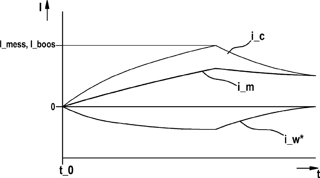
[0024] figure 2 shows a typical electromagnetic actuator 10 ( figure 1 ) The simplified equivalent circuit diagram of the magnetic circuit 11.

[0025] This equivalent circuit diagram has a resistance R_c representing the ohmic resistance of the primary coil of electromagnetic actuator 10 . Connected in series with this ohmic ...


PUM


Abstract

The invention relates to a method for operating an electromagnetic actuator, in particular of a fuel injection valve of an internal combustion engine of a motor vehicle, in which method the electromagnetic actuator is activated during an activation process in order to influence an operating state of the actuator. According to the invention, a state, which is present in particular at the start of the activation process, of a magnetic circuit (11) of the electromagnetic actuator is taken into consideration in the activation of the electromagnetic actuator.

Description

technical field [0001] The invention relates to a method for operating an electromagnetic actuator, in particular a fuel injection valve of an internal combustion engine of a motor vehicle, wherein the electromagnetic actuator is activated during an activation process in order to influence the operating state of the actuator. [0002] Furthermore, the invention also relates to a control device for carrying out such an operating method. Background technique [0003] A method of the type mentioned at the outset is already known from DE 101 38 483 A1. In order to increase the precision when activating the electromagnetic actuator, known methods provide that the electromagnetic actuator is subjected to a current pulse prior to the actuation and that the actuation is corrected based on a quantity that characterizes the duration of the current pulse. This achieves that the excitation duration is constant for several excitation processes with different supply voltages. [0004] A...

Claims


Application Information

Patent Timeline
Patent Type & Authority Patents(China)
IPC IPC(8): F02D41/20F02D41/24H01F7/18
CPCF02D2041/2058F02D2041/2003H01F7/1844F02D2041/2051F02D41/28F02D41/20F02D2041/2031
Inventor K.约斯R.施吕特J.诺伊贝格H.克默H.拉普H.哈梅多维克J.克尼希A-T.黄B.维歇特W.菲舍尔S.佐伊林A.希尔申海因
Owner ROBERT BOSCH GMBH
Learn More