Power conversion apparatus, grid connection apparatus, and grid connection system

A technology of power conversion device and circuit, which is applied in the direction of high-efficiency power electronic conversion, output power conversion device, circuit device, etc., and can solve problems such as low reliability and abnormal output voltage

Inactive Publication Date: 2012-05-23
SANYO ELECTRIC CO LTD
View PDF5 Cites 3 Cited by
  • Summary
  • Abstract
  • Description
  • Claims
  • Application Information

AI Technical Summary

Problems solved by technology

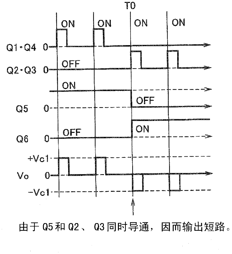
[0009] In this way, in a power conversion device provided with an output short-circuit circuit, there is a possibility that an abnormality occurs in the output voltage of the inverter circuit at the timing when the polarity of the output voltage of the inverter circuit should be switched, that is, in the vicinity of the zero cross point. low sex problem

Method used


Image

  • Power conversion apparatus, grid connection apparatus, and grid connection system
  • Power conversion apparatus, grid connection apparatus, and grid connection system
  • Power conversion apparatus, grid connection apparatus, and grid connection system

Examples


no. 2 Embodiment approach

[0084] Next, a second embodiment will be described. In the following second to fifth embodiments, differences from the first embodiment will be described.

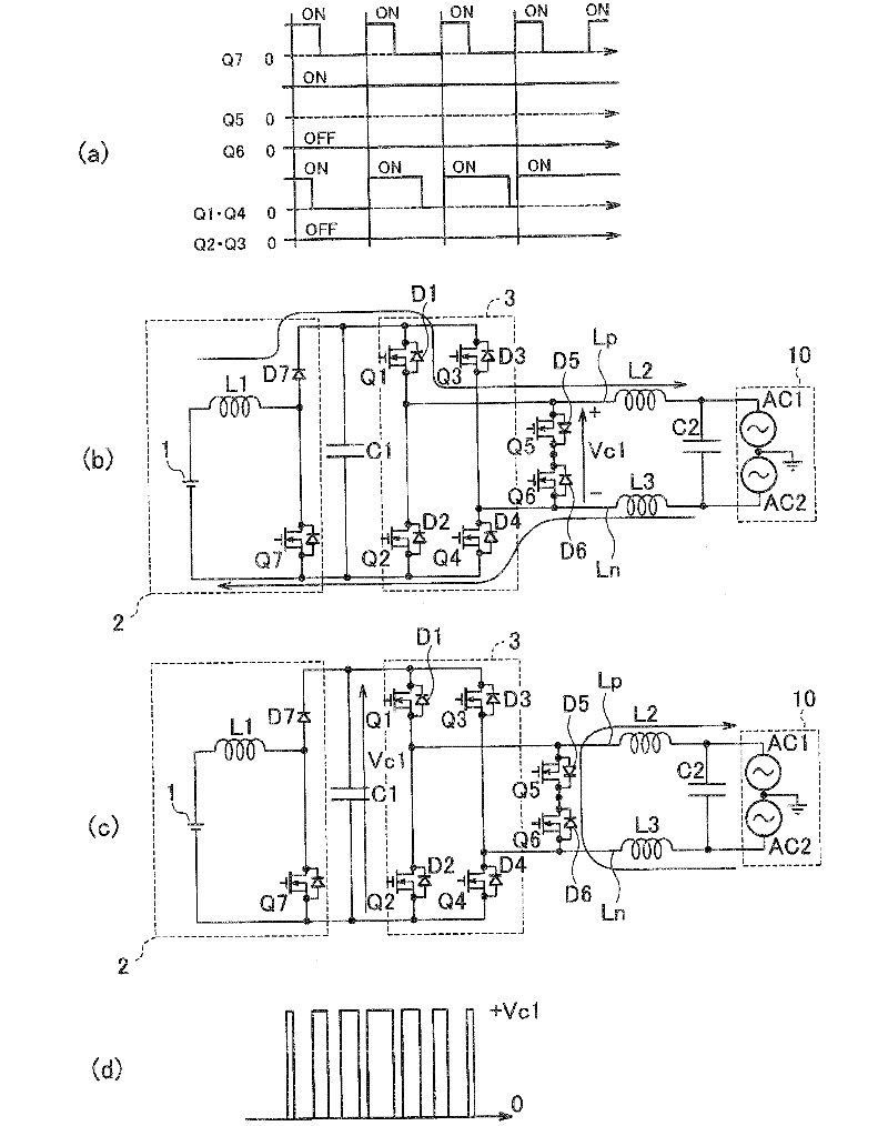
[0085] In the above-mentioned first embodiment, the switching elements Q5 and Q6 of the output short-circuit circuit 4 are switched from the on state to the off state at a timing earlier than the zero cross point. A surge voltage (surge voltage) will be generated after Q5 and Q6 are switched to the off state.

[0086] refer to Figure 6 , taking the action when the polarity of the output voltage Vo is switched from positive to negative as an example to describe the above problem. Figure 6 (a) is a diagram showing the flow of current before switching the switching element Q5 to an off state, Figure 6 (b) is a diagram showing the flow of current after switching the switching element Q5 to the OFF state, Figure 6 (c) is a timing chart when a surge voltage is generated.

[0087] Such as Figure 6 As shown in (a), befo...

no. 3 Embodiment approach

[0099] Next, a third embodiment will be described. In the first and second embodiments described above, since the timing for stopping the switching operation of the switching element of the inverter circuit 3 and the timing for switching the switching element of the output short-circuit circuit 4 from the on state to the off state Since the timing is set earlier than the zero-cross point, the current supplied to the load via the switching element of the output short-circuit circuit 4 decreases. However, since this reduction can be supplied by the capacitor C2 of the filter circuit 5, there is no problem in circuit operation.

[0100] Utilizing this property, in the third embodiment, such as Figure 9 As shown, a current detector 11 for detecting the current on the output side of the filter circuit 5 is provided, and the control circuit 20 performs control based on the current detected by the current detector 11 . Thus, even if the timing of stopping the switching operation o...


PUM


Abstract

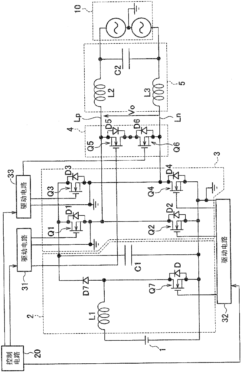
A power conversion apparatus is provided with an inverter circuit, an output short-circuiting circuit, and a control circuit. The inverter circuit comprises a first inverter switch that is configured so as to generate a first polarity voltage from DC voltage, and a second inverter switch that is configured so as to generate a second polarity voltage from the DC voltage. The output short-circuiting circuit comprises a first short-circuiting switch that is configured so as to short-circuit a power supply line that outputs the first polarity voltage, out of a pair of power supply lines, and a second short-circuiting switch that is configured so as to short-circuit a power supply line that outputs the second polarity voltage, out of the pair of power supply lines. Upon switching the polarity from the first polarity to the second polarity, the control circuit turns off the first short-circuiting switch before the timing whereby the second inverter switch is turned on.

Description

technical field [0001] The present invention relates to a power conversion device, a grid connection apparatus and a grid connection system for converting DC voltage from a DC power source such as a solar cell or a fuel cell into an AC voltage. Background technique [0002] Conventionally, such a power conversion device has a DC-DC conversion circuit that boosts a DC voltage from a DC power supply, an inverter circuit that converts the output voltage of the DC-DC conversion circuit into an AC voltage, and converts the AC voltage into an AC voltage. A voltage is output to a pair of power supply lines; a filter circuit that removes a high-frequency component contained in an output voltage of the inverter circuit; and a control circuit that controls the inverter circuit and an output short-circuit circuit. [0003] In recent years, a circuit system has been proposed in which an output short-circuit circuit configured to short-circuit the pair of power supply lines is provided t...

Claims


Application Information

Patent Timeline
Patent Type & Authority Applications(China)
IPC IPC(8): H02M7/48H02M3/155
CPCH02M2001/007H02J3/381H02M7/48H02M1/126H02M1/38H02M7/5387H02M7/5395H02M1/0048H02M1/007Y02B70/10
Inventor 江阪纮一郎伊藤和雄
Owner SANYO ELECTRIC CO LTD
Why Eureka
Try Eureka