Cylinder head with fluid cooling device and method for cooling the cylinder head

A fluid cooling and cylinder head technology, applied in the direction of cylinder head, cylinder, engine components, etc., can solve the problems of increasing danger, achieve the effect of preventing excessive temperature and improving thermal conductivity

Active Publication Date: 2015-10-21
GM GLOBAL TECH OPERATIONS LLC
View PDF6 Cites 0 Cited by
  • Summary
  • Abstract
  • Description
  • Claims
  • Application Information

AI Technical Summary

Problems solved by technology

The risk of harmful fuel deposits on the nozzles is thus also increased

Method used


Image

  • Cylinder head with fluid cooling device and method for cooling the cylinder head
  • Cylinder head with fluid cooling device and method for cooling the cylinder head

Examples


Embodiment Construction

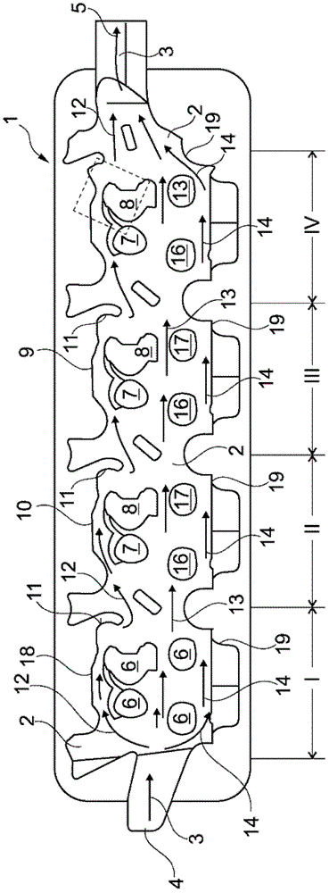
[0019] figure 1 is a schematic illustration of a coolant jacket 2 of a cylinder head 1 of an internal combustion engine with four cylinder zones I, II, III and IV. In the coolant jacket 2 there are four channels 6 each leading to four cylinder regions, wherein the first channel 7 accommodates the nozzles, and the second channel 8 arranged behind the first channel 7 in the flow direction has a spark plug arrangement, In this case, the channels 7 and 8 of the four cylinder ranges I to IV have a third channel 16 with intake valves leading into the individual cylinders and a fourth channel 17 with exhaust valves from the individual cylinders. The coolant jacket 2 is delimited by outer walls 18 and 19 .

[0020] The third and fourth channels 16 and 17 are likewise arranged one behind the other and form a second row of channels in the coolant jacket 2 . The coolant jacket 2 has a coolant inlet 4 and a coolant outlet 5 . The main flow path 3 flows from the coolant inlet 4 to the c...


PUM


Abstract

A cylinder head is provided with liquid cooling system and a method for cooling the cylinder head. The cylinder head includes, but is not limited to a liquid jacket in which a coolant flows along a main flow pathway from a coolant inlet to a coolant outlet. The liquid jacket is interrupted between the coolant inlet and coolant outlet by portals to cylinders of an internal combustion engine. A second portal is arranged in a flow shadow of a first portal. The cylinder head in the liquid jacket exhibits a flow guide wall with a constriction of the flow cross section, and a baffle plate, which is arranged in the direction of the main flow pathway, downstream from the flow guide wall. The baffle plate is designed to divert a coolant flow branch in a direction of flow transverse to the main flow pathway, toward the second portal.

Description

technical field [0001] The invention relates to a cylinder head with a fluid cooling device and a method for cooling the cylinder head. The cylinder head has a fluid jacket in which coolant flows in a main flow path from a coolant inlet to a coolant outlet. Between the coolant inlet and the coolant outlet, the fluid jacket is interrupted by channels leading to the cylinders of the internal combustion engine. In the flow shadow area of ​​the first channel ( ) with a second channel. Background technique [0002] Due to this flow shadow, the second channel is not cooled as strongly as the first channel. It is provided here that in the first channel leading to the cylinder there is a nozzle which is completely cooled by the fluid jacket. In contrast, an ignition device is provided in the second channel, which is now subjected to an increased temperature load in the flow shadow region of the nozzle when it is arranged parallel to the camshaft. An increase in spark plug temp...

Claims


Application Information

Patent Timeline
Patent Type & Authority Patents(China)
IPC IPC(8): F02F1/24F02F1/42F02F1/26
CPCF02F1/40
Inventor W.施利特P.西格S.沃格尔C.陶克尔M.克莱因R.莫克尔J.齐默尔曼
Owner GM GLOBAL TECH OPERATIONS LLC
Why Eureka
Try Eureka