Eureka AIR delivers breakthrough ideas for toughest innovation challenges, trusted by R&D personnel around the world.

Aerostatic bearing and application thereof

A technology of air static pressure bearing and pressure equalizing groove, which is applied in the directions of bearings, shafts and bearings, mechanical equipment, etc., can solve the problems of mutual interference of air flow of combined air bearings and insufficient bearing capacity of a single air bearing, and meet the requirements of reducing manufacturing accuracy. Effect

Inactive Publication Date: 2012-05-30
张建军
View PDF3 Cites 1 Cited by
  • Summary
  • Abstract
  • Description
  • Claims
  • Application Information

AI Technical Summary

Problems solved by technology

[0005] The invention mainly solves the technical problem that the bearing capacity of a single air bearing is not large enough and the airflow of the combined air bearing interferes with each other, and provides a partitioned combined air bearing with pressure relief grooves

Method used


Image

  • Aerostatic bearing and application thereof
  • Aerostatic bearing and application thereof
  • Aerostatic bearing and application thereof

Examples


Embodiment 1

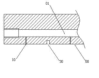
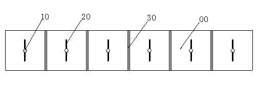
[0026] An aerostatic bearing with a rectangular single-row orifice slider. There is an air inlet channel 01 running through the middle of the slider. The air channel 01 is vertically connected with Ф0.4 orifice 10, each of the two sides of each orifice 10 has a V-shaped pressure equalizing groove 20 with a width of 0.2 mm, and the middle of each two orifices 10 is provided with a width of 0.4 mm. square pressure relief groove 30, see attached figure 1 , 2 .

[0027] When working, as the slider of the mobile carrier, the working surface 00 is on the guide rail, and the high-pressure air enters the orifice 10 through the air intake channel 01, and an air film is formed around the pressure equalization groove 20 on both sides of the orifice 10 to support the slide. The block floats, because the air film periphery is open, the surface of the guide rail is usually much larger than the working surface of the slider, so the air flow diffuses to the outside along the working surface...

Embodiment 2

[0029] An aerostatic bearing, which has a slider with double rows of throttle holes 10, each throttle hole 10 is evenly distributed with "ten"-shaped pressure equalizing grooves 20, and the working surface of each throttle hole 10 is 00 It is a circular structure, surrounded by a pressure relief groove 30 with a depth of 1 mm, see the attached image 3 .

[0030] Other parameters and working principles are the same as those in Embodiment 1, and will not be repeated here.

Embodiment 3

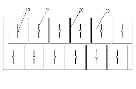
[0032] An aerostatic bearing, which has a slider with double rows of staggered orifices 10, each orifice 10 is evenly distributed with "one"-shaped pressure equalizing grooves 20, and the orifices 10 are evenly distributed with 1.2 mm deep pressure relief groove 30, see attached Figure 4 .

[0033] Other parameters and working principles are the same as those in Embodiment 1, and will not be repeated here.


PUM


Abstract

The invention relates to provide an aerostatic spring and an application thereof. The aerostatic spring comprises a guide rail and a sliding block, wherein the sliding block is provided with an air inlet channel in which throttling holes are connected, and the throttling holes are communicated with a working surface of the sliding block. The aerostatic spring is characterized in that pressure-releasing slots are arranged among the throttling holes on the working surface and are communicated with the end surface of the working surface of the sliding block. Simultaneously, the invention also provides a method for applying the aerostatic spring to a long-distance guide rail. The aerostatic bearing and the application thereof, disclosed by the invention, have the advantages that: the pressure-releasing slots are arranged among the throttling holes of the sliding block, equivalently a plurality of parallel aerostatic bearings are arranged on one sliding block, thus a problem of air vibration in the sliding block with a plurality of throttling holes is solved; simultaneously, the sliding block with the plurality of throttling holes can be applied to long-distance jointed guide rails, allows jointed parts of the guide rails to have tiny gaps, and reduces manufacturing precision requirements of the traditional long-distance guide rails.

Description

technical field [0001] The invention relates to the field of sliding bearings, in particular to an air static pressure bearing and its application. Background technique [0002] As we all know, aerostatic bearings are widely used in the field of mechanical transmission and guiding technology due to their simple structure, low operating cost and high precision. This kind of air film is used to isolate the relative moving support surface and the supported surface, so the formation, maintenance and pressure relief technology of the air film should be continuously explored. For example, the Chinese patent CN2670900Y relates to a mosaic static pressure thrust air bearing for a coordinate measuring machine, which consists of: a jewel bearing, which is characterized in that: the jewel bearing is processed with an orifice, and the jewel bearing The bearing is pressed into the metal main body and is flush with the end surface, and the metal main body is glued and pressed into the ai...

Claims


Application Information

Patent Timeline
IPC IPC(8): F16C32/06
Inventor 张建军
Owner 张建军
Why Eureka
Eureka Blog
Learn More