Method for correcting flat field of two-dimensional optical detection

A technology of optical detection and flat-field correction, which is applied in the input/output process of data processing, instruments, and electrical digital data processing, etc. Problems such as chromaticity and uneven chromaticity of the LED unit matrix to be tested

Active Publication Date: 2012-05-30
致茂电子(苏州)有限公司
View PDF2 Cites 7 Cited by
  • Summary
  • Abstract
  • Description
  • Claims
  • Application Information

AI Technical Summary

Problems solved by technology

[0010] The first purpose of the present invention is to solve the problem in the prior art that the flat-field correction image (Flat-Field Frame) captured by the planar light source cannot completely correspond to the luminous field type of the LED unit to be tested, resulting in the inability to completely calibrate the LED to be tested. The problem of non-uniform light intensity in the detection image of the unit's deviation from the orthographic projection
[0011] The second purpose of the present invention is to solve the problem that in the prior art, the flat-field corrected image captured by the planar light source cannot reflect the phenomenon of uneven chromaticity of the LED unit matrix to be tested, and cannot correct the deviation from the normal projection detection image. The problem of uneven color

Method used


Image

  • Method for correcting flat field of two-dimensional optical detection
  • Method for correcting flat field of two-dimensional optical detection
  • Method for correcting flat field of two-dimensional optical detection

Examples


Embodiment Construction

[0046] Below in conjunction with accompanying drawing, structural principle and working principle of the present invention are specifically described:

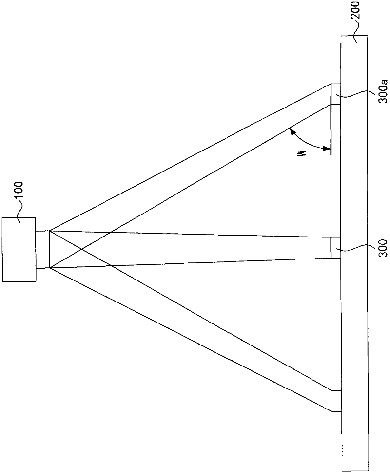
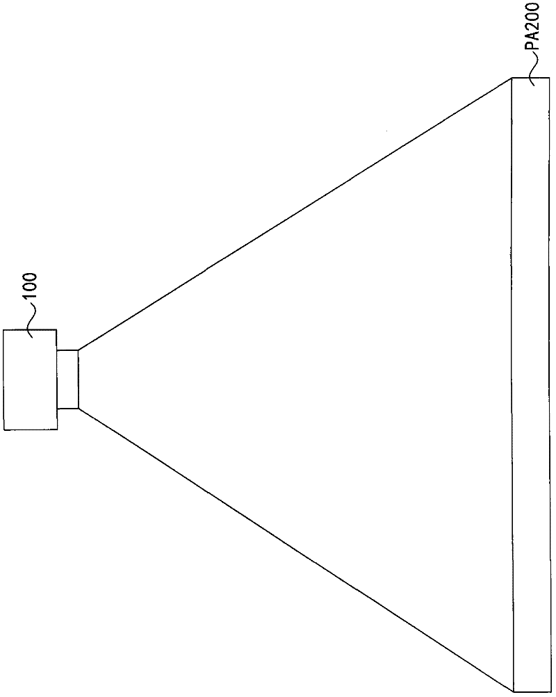
[0047] Please refer to the description of the current flat-field correction method for two-dimensional optical detection in the prior art, and refer to figure 1 and figure 2 , which are respectively a schematic diagram of detection by a two-dimensional optical detection system, and a schematic diagram of the operation of a flat-field correction method for two-dimensional optical detection in the prior art. As described in the prior art, the current flat-field correction method for two-dimensional optical detection cannot completely correct the problem of uneven light intensity and light chromaticity caused by deviation from the normal projection in the detection image.

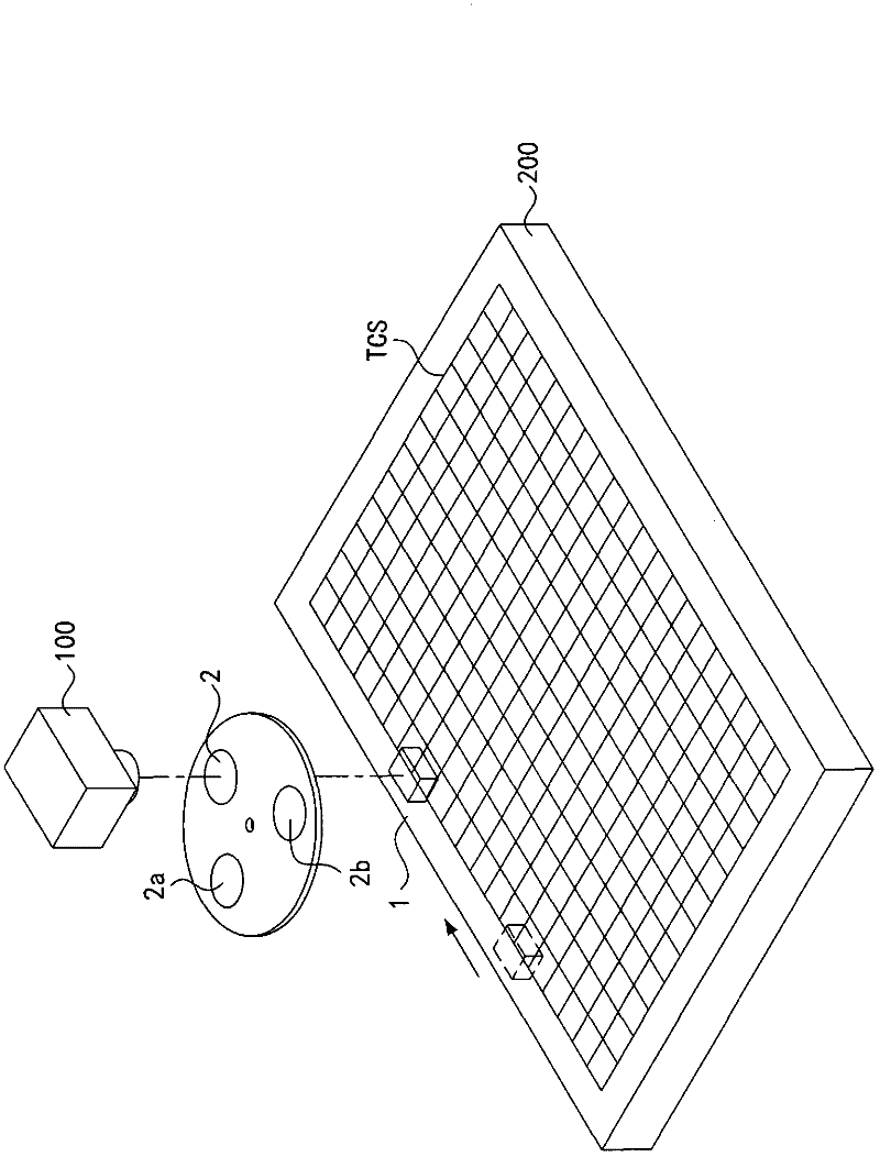
[0048] The present invention provides a novel flat-field correction method for two-dimensional optical detection, which can induce at least one luminous bod...


PUM


Abstract

The invention relates to a method for correcting a flat field of two-dimensional optical detection. A first optical filter is arranged between a CCD (Charge Coupled Device) and at least one reference illuminator. The reference illuminator is moved relative to the CCD, so as to utilize the CCD to capture a plurality of individual images and integrate a flat field message. Accordingly, a first light intensity correcting field profile is calculated, thereby obtaining a first light intensity correcting rate corresponding to each image coordinate in an image coordinate system of CCD. After a deviated projecting detection image of at least one to-be-detected illuminator is captured by the CCD, a corrected light intensity value corresponding to each image coordinate in the deviated projecting detection image is calculated according to the first light intensity correcting rate, so as to obtain a light intensity correcting detection image.

Description

technical field [0001] The invention relates to a correction method for optical detection, in particular to a flat-field correction method for two-dimensional optical detection. Background technique [0002] In a two-dimensional optical inspection system, when the same object to be measured is located at different positions on the plane to be measured, the same detection results should be detected in order to maintain the consistency of detection, and then accurately detect the defects of the object to be measured itself . However, in the actual inspection, the consistency of the inspection will be affected by factors such as the vignetting effect of the lens, the sensitivity difference of different pixels of the charge-coupled device, the unevenness of the filter itself, and dust contamination, resulting in errors in the inspection . [0003] see figure 1 , which is a schematic diagram of a two-dimensional optical detection system for detection. As shown in the figure, ...

Claims


Application Information

Patent Timeline
Patent Type & Authority Applications(China)
IPC IPC(8): G06F3/042
Inventor 翁义龙杨欣泰黄俊霖胡哲郕
Owner 致茂电子(苏州)有限公司
Why Eureka
Try Eureka