
System and method for managing difficult airways

a technology of difficult airways and systems, applied in the field of endotracheal intubation of patients, can solve the problems of difficult airways, difficult airways, difficult to precisely control fiberoptic scopes, etc., and achieve the effect of facilitating tube placemen

Active Publication Date: 2007-06-07
THE COOPER HEALTH SYST
View PDF20 Cites 77 Cited by
  • Summary
  • Abstract
  • Description
  • Claims
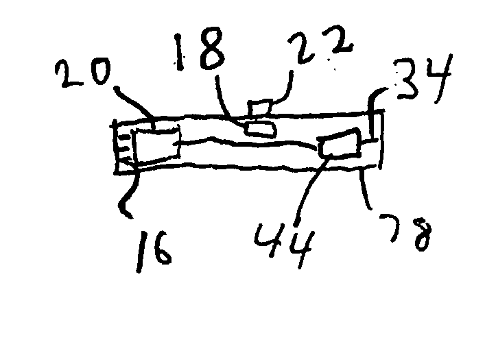
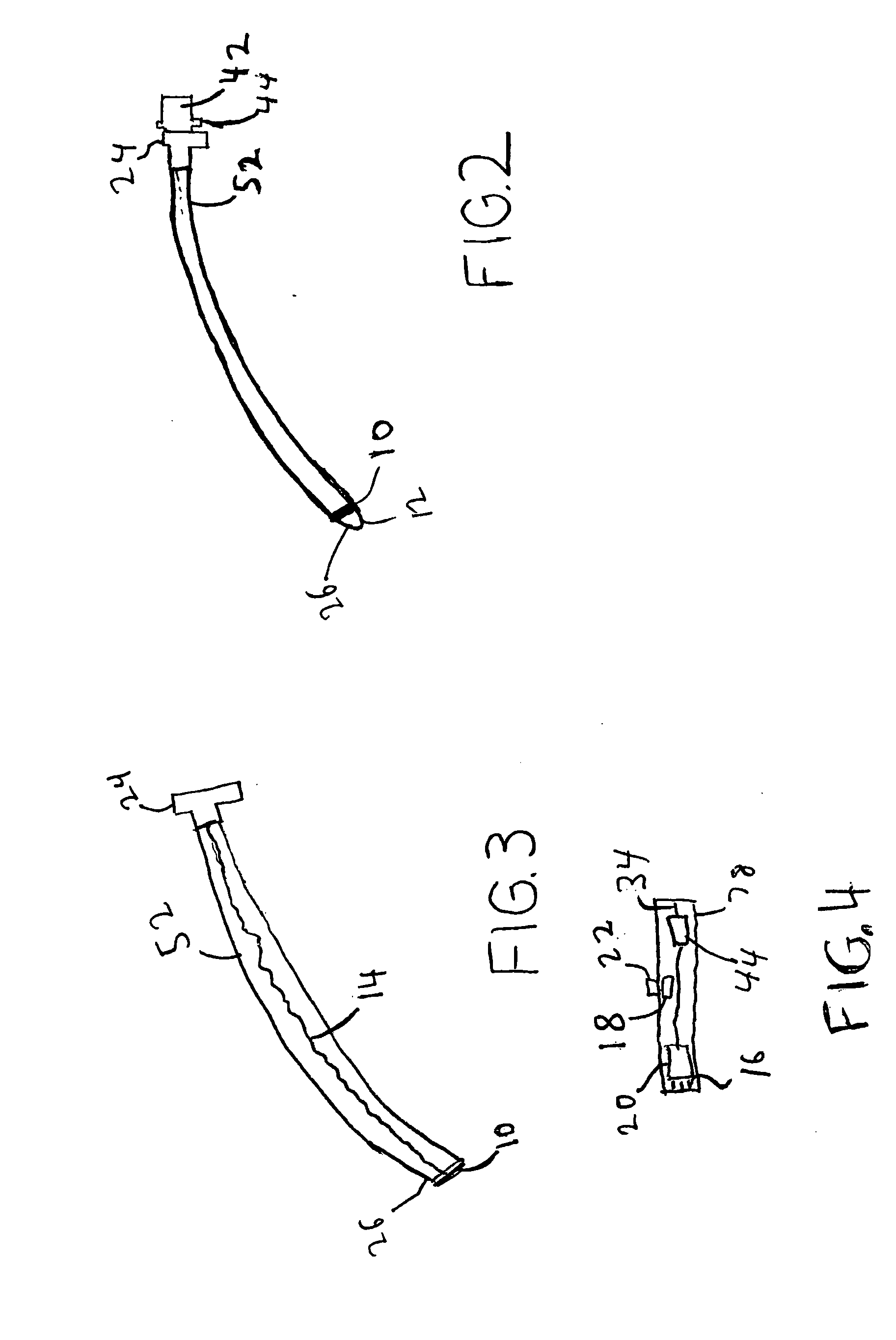
  • Application Information

AI Technical Summary

Benefits of technology

[0007] It is another object of the invention to provide a system which avoids the problems associated with fiberoptic scopes currently used for visualization of trachea during endotracheal intubations. In some aspects, the present invention allows simultaneous access to two useful perspectives when performing endotracheal intubation of difficult airways.
[0010] The stylet can be a tube with a lumen through the center, or it can be a solid wire. In some instances, the stylet may have more than one lumen, for example, in embodiments which include an optional illumination means, a separate lumen may be provided to carry the conductor means such as wires from the source of electrical power to the illumination means such as an LED or xenon lamp. The stylet is primarily constructed of a malleable material, including without limitation, copper or aluminum. In some embodiments, the stylet is coated with plastic material, for example, polyethylene molded in the dimensions of the stylet. In some embodiments, a CCD imaging means at the distal end is connected to a wireless transmitter at the proximal end by means of one or more cables within the stylet lumen or on the between the stylet and the plastic covering, when present. In some embodiments, the coaxial cable terminates at a connector at the proximal end of the stylet, and the wireless transmitter is in a housing assembly which has a connector designed to mate with the connector at the proximal end of the stylet. The CCD and wireless transmitter in the stylet assembly may be powered by a battery. In some embodiments, the battery is within the wireless transmitter assembly. The visualization device may also include a power supply. In some embodiments, the power supply is a rechargeable battery. If the stylet has a lumen, it can be used to introduce a thin, flexible guide wire through the vocal cords and into the trachea under direct vision. This can facilitate tube placement under difficult circumstances.
[0011] The wireless transmitter may be permanently connected to the stylet or within the stylet itself. In some embodiments, the transmitter is located in a separate housing along with a power supply and antenna. In some embodiments, the transmitter is part of the stylet itself rather than in a separate housing connected to the stylet by plug and socket connectors. The housing may have a socket or plug at one end which matches and engages a corresponding plug or socket on the stylet. The transmitter housing may include a switch so that the transmitter can be turned on and off, and it may have means for easy replacement of the battery, or it may have a separate connector for recharging the battery. In some embodiments, the wireless transmitter housing does not come in contact with the patient and so does not have to be sterilized. The housing may be sterilizable, if desired.

Problems solved by technology

The “difficult airways” situation arises frequently when the patient has a short mandible, impaired neck mobility, a short neck, trismus of the jaw, or a swollen tongue.
Other situations of difficult airways arise when the patient is obese or is wearing a halo cervical fixation device because of a cervical fracture.
However, some fiberoptic scopes are difficult to precisely control, making it difficult to visualize the vocal cords.
Furthermore, fiberoptic scopes typically do not create by themselves a pocket of air inside the pharynx through which structures can be visualized.
Furthermore, in some situations when the operator focuses one eye through the eyepiece and closes the other eye, the operator may lose the natural, global, intuitive perspective ordinarily gained from looking directly into the mouth with a conventional rigid laryngoscope blade of known extension.

Method used


Image

  • System and method for managing difficult airways
  • System and method for managing difficult airways
  • System and method for managing difficult airways

Examples


Embodiment Construction

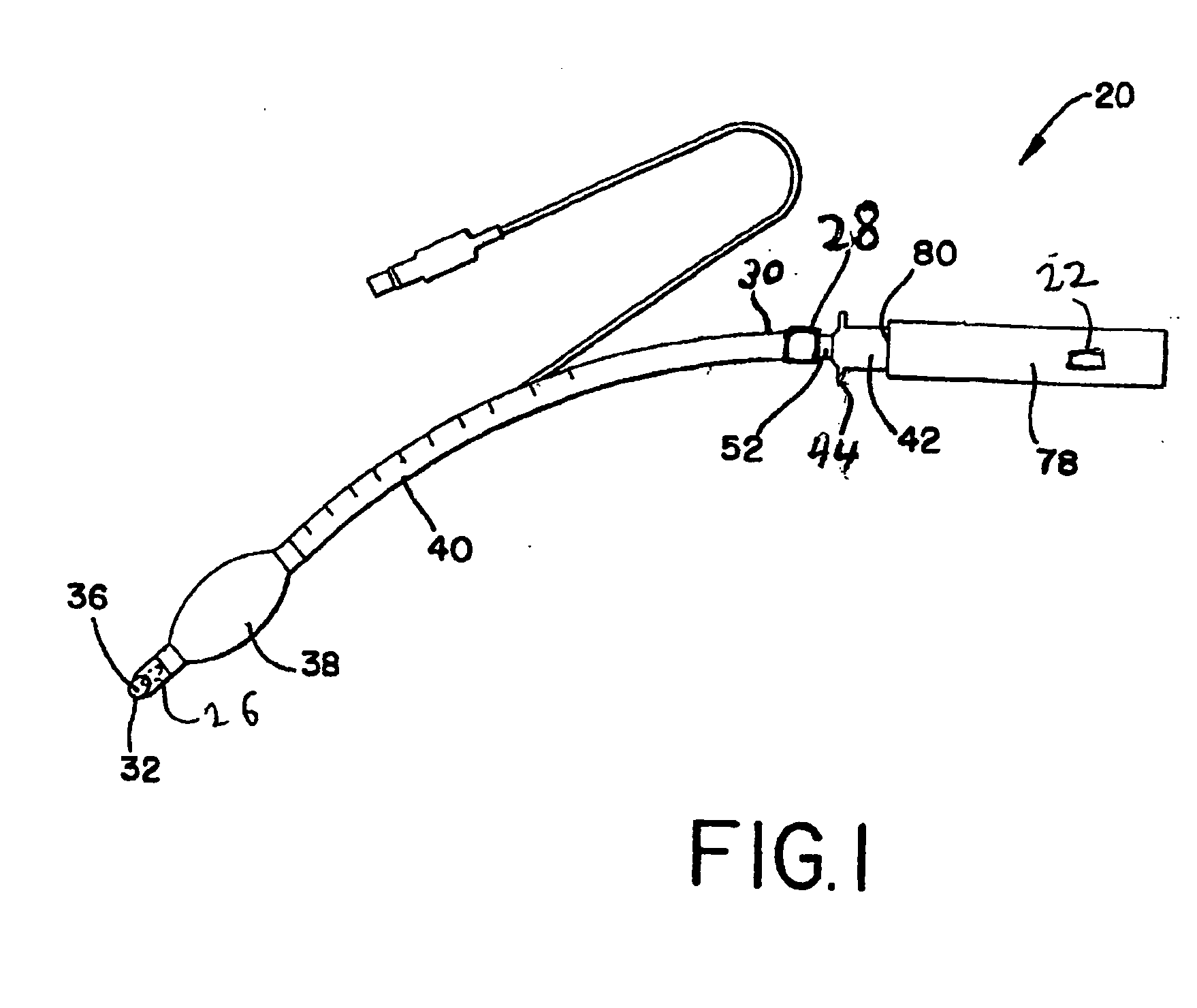
[0025] Referring first to FIG. 1 of the drawings, an embodiment of an ETT-stylet-wireless transmitter assembly 20 is shown. The assembly 20 includes an ETT 40, stylet 52, and wireless transmitter housing 78. The wireless transmitter housing 78 includes a plug 80 which engages socket assembly 42, which in turn is press fit to the stylet 52. The wireless transmitter housing 78 locks onto the socket assembly 42 and can be unlocked by pressing a tab (not shown) on the socket assembly 42.

[0026] The stylet is made of aluminum tube in this embodiment. In some embodiments, the stylet is made of other malleable materials such as copper. The stylet can be solid wire instead of tubular.

[0027] The stylet is of a size and shape so it can be inserted through the center of the ETT 40, as illustrated, so that the stylet distal end 36 is close to the ETT distal end 32. The stylet should fit smoothly and easily into the ETT 40, and then the ETT 40 with stylet 52 inside can be bent into a curve or o...


PUM


Abstract

A system and method for endotracheal intubation of airways are disclosed. A malleable stylet having a distal end and a proximal end, a charged coupled device (CCD) at the distal end and a transmitter, at or near the proximal end or connected to the proximal end of the stylet with connectors, transmits video to a visualization device comprising a receiver means, a display means, and a display support adapted to be worn on an operator in a position so that the operator can view the display with one eye while simultaneously viewing the airway directly. The display support is typically worn on the head of a physician. A second display can be worn by a student or observer. In some instances, the transmitter means and receiver means are wireless.

Description

FIELD OF THE INVENTION [0001] This invention relates generally to the field of endotracheal intubation of patients by a medical professional, and, in some aspects, relates to intubation of difficult airways. BACKGROUND OF THE INVENTION [0002] A conventional method of endotracheal intubation is to first use a MacIntosh or Miller laryngoscope to move the patient's tongue out of the way, visualize the vocal cords, and then to insert an endotracheal tube (ETT) with a malleable stylet inside. Once the ETT is placed in proper position, the stylet is removed and the ETT is connected, for example, by means of a 15 mm connector, to a circle system to supply oxygen and remove carbon dioxide. [0003] For the situation of “difficult airways,” i.e., when the uvula can not be seen by inspection with the mouth wide open and the tongue extended, various alternative procedures have been used. The “difficult airways” situation arises frequently when the patient has a short mandible, impaired neck mobi...

Claims


Application Information

Patent Timeline
Patent Type & Authority Applications(United States)
IPC IPC(8): A61B1/04
CPCA61B1/00016A61B1/00048A61B1/267A61M16/0488A61M16/0434A61M16/0486A61B1/00108
Inventor HIRSH, ROBERT
Owner THE COOPER HEALTH SYST
Learn More