Novel optical architectures for microvolume laser-scanning cytometers

a micro-volume laser and optical architecture technology, applied in the direction of optical radiation measurement, spectral modifiers, radiation measurement, etc., can solve the problems of limiting the speed and sensitivity performance of prior art systems, preventing further improvement in sensitivity and measurement speed, and commonly used pmt detectors with low quantum efficiency, etc., to reduce the power density in each spot, minimize sensitivity and laser power limitations, and high quantum efficiencies

Inactive Publication Date: 2005-03-17
PPD BIOMARKER DISCOVERY SCI
View PDF22 Cites 76 Cited by
  • Summary
  • Abstract
  • Description
  • Claims
  • Application Information

AI Technical Summary

Benefits of technology

[0014] The preferred embodiment of the present invention uses CCD detectors (instead of PMTs) as non-imaging light-detecting devices in a confocal scanning architecture, where an array of laser spots is scanned across the sample, instead of a single spot. Two features of this invention solve the limitations described above. Firstly, the high power laser excitation is divided into multiple spots, thus reducing the power density in each spot and minimizing sensitivity and laser power limitations due to fluorophore saturation. Secondly, the CCD is used in a non-imaging mode, by defining multiple effective confocal apertures as “binned” regions of pixels on the 2 dimensional surface of the device. Each binned region is matched to an excitation laser spot which is focused into the sample. This architecture retains the controllable depth of field of a PMT-based confocal spot scanner, but also takes advantage of the very high quantum efficiencies available with CCD detectors.

Problems solved by technology

Two issues typically limit the speed and sensitivity performance of prior art systems.
Firstly, commonly used PMT detectors have low quantum efficiencies, especially in the red to near infrared region of the optical spectrum.
Secondly, these systems typically scan a focused laser spot to excite fluorescent emission in the sample.
However, beyond certain saturating power densities (power per unit area of the laser spot), the excitation source saturates the fluorescent labels, preventing further improvement in sensitivity and measurement speed.

Method used


Image

  • Novel optical architectures for microvolume laser-scanning cytometers
  • Novel optical architectures for microvolume laser-scanning cytometers
  • Novel optical architectures for microvolume laser-scanning cytometers

Examples


Embodiment Construction

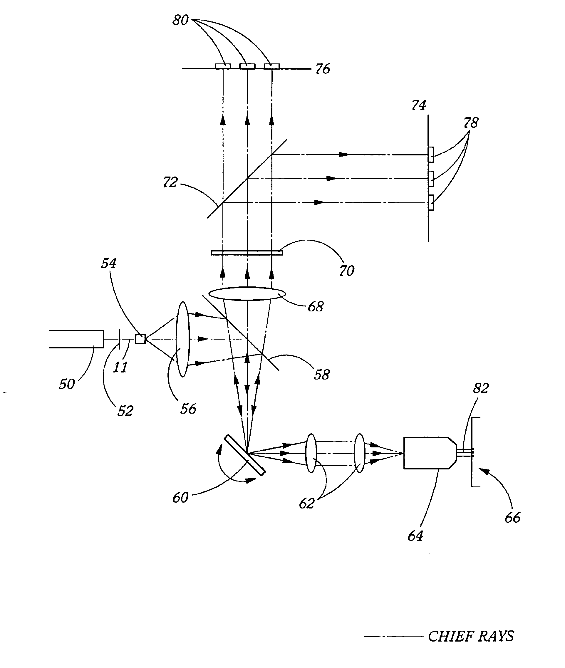
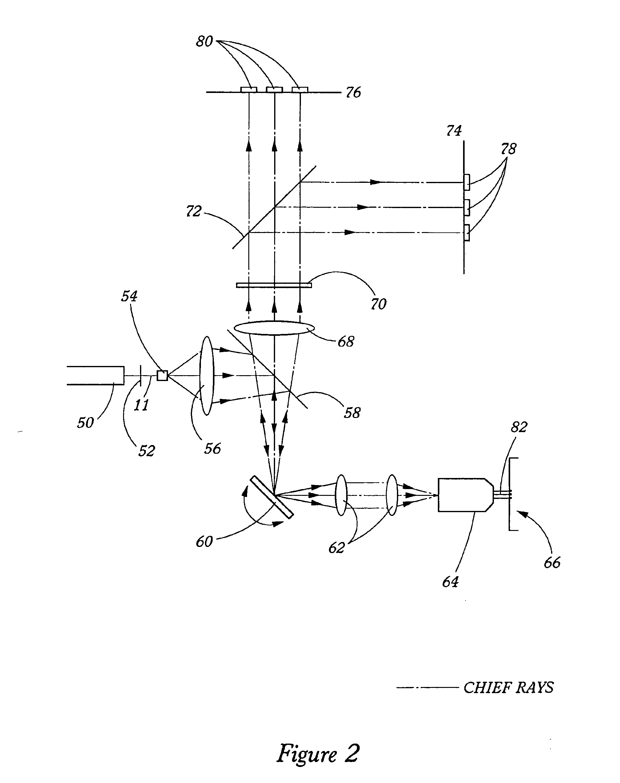
[0025] The present invention provides spectroscopy methods and instrumentation with a number of novel optical configurations that allow multichannel images to be acquired quickly, and / or with time-resolution of the individual fluorophore emissions. In preferred embodiments, the invention uses CCDs as light detectors, wherein groups of pixels on the CCD form bins that are imaged onto the sample by the scanning optics. In preferred embodiments, each bin functions as a confocal aperture. The size of the bin determines the width of the cone of emitted light that is detected, and hence the greater the bin size, the greater the depth of field. Light that falls on the CCD outside of the bin is not detected. Hence, each bin functions in the same way as a mechanical confocal aperture. In preferred embodiments, the invention uses an array of laser spots to scan the sample simultaneously in multiple locations. Emitted light from each spot is imaged onto a separate confocal CCD bin, and the ima...


PUM

PropertyMeasurementUnit
anglesaaaaaaaaaa
scan widthaaaaaaaaaa
quantum efficienciesaaaaaaaaaa

Abstract

Methods and instrumentation for performing charge coupled device (CCD)-based confocal spectroscopy with a laser spot array are provided. The methods and instruments of the invention are useful in any spectroscopic application, including, but not limited to, microscopy and microvolume laser scanning cytometry (MLSC).

Description

PRIORITY APPLICATION DATA [0001] This application is a continuation of U.S. patent application Ser. No. 10 / 635,917, filed Aug. 5, 2003, now U.S. Pat. No. 6,800,860, which is a divisional of U.S. patent application Ser. No. 09 / 378,259, filed Aug. 20, 1999, now U.S. Pat. No. 6,603,537, which claims the benefit of U.S. Provisional Patent Application Ser. No. 60 / 097,506, filed Aug. 21, 1998, entitled “Laser-scanner confocal time-resolved fluorescence spectroscopy system.” Each aforementioned priority application is incorporated herein by reference in its entirety.BACKGROUND OF THE INVENTION [0002] Microvolume laser scanning cytometry (MLSC) is a method for analyzing the expression of biological markers in a biological fluid. See, e.g., U.S. Pat. Nos. 5,547,849 and 5,556,764; Dietz et al., Cytometry 23:177-186 (1996); U.S. Provisional Application 60 / 144,798, filed Jul. 21, 1999, each of which is incorporated herein by reference. A sample, such as blood, is incubated in a capillary with o...

Claims


Application Information

Patent Timeline
Patent Type & Authority Applications(United States)
IPC IPC(8): G01N21/64C12M1/34C12Q1/06G01N15/14G01N33/483
CPCG01N15/1434G01N15/1484G01N15/1475G01N21/64
Inventor DIETZ, LOUIS J.WALTON, IANNORTON, SCOTT
Owner PPD BIOMARKER DISCOVERY SCI
Why Eureka
Try Eureka