Eureka AIR delivers breakthrough ideas for toughest innovation challenges, trusted by R&D personnel around the world.

Neutron tubes

a technology of neutron tubes and tubes, which is applied in the field of neutron tubes, can solve the problems of limited neutron production, limited neutron yield, and limited neutron yield, and achieve the effects of reducing energy loading, increasing neutron flux, and increasing surface area

Inactive Publication Date: 2008-03-11
RGT UNIV OF CALIFORNIA
View PDF20 Cites 28 Cited by
  • Summary
  • Abstract
  • Description
  • Claims
  • Application Information

AI Technical Summary

Benefits of technology

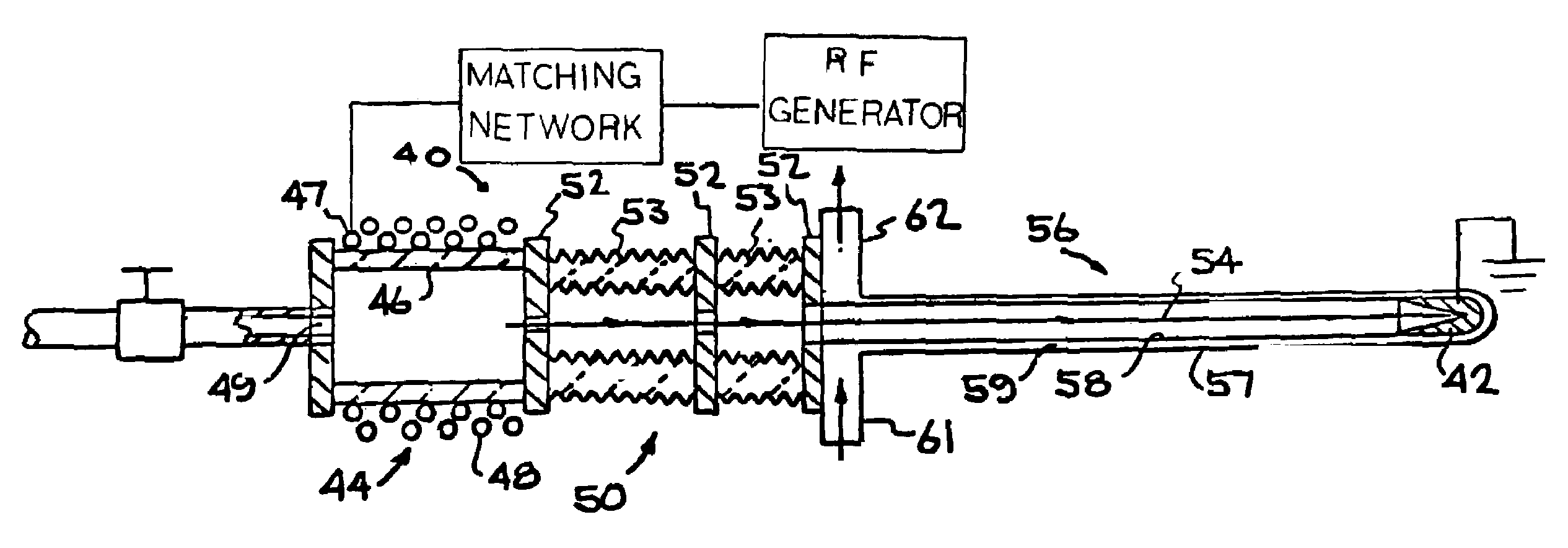
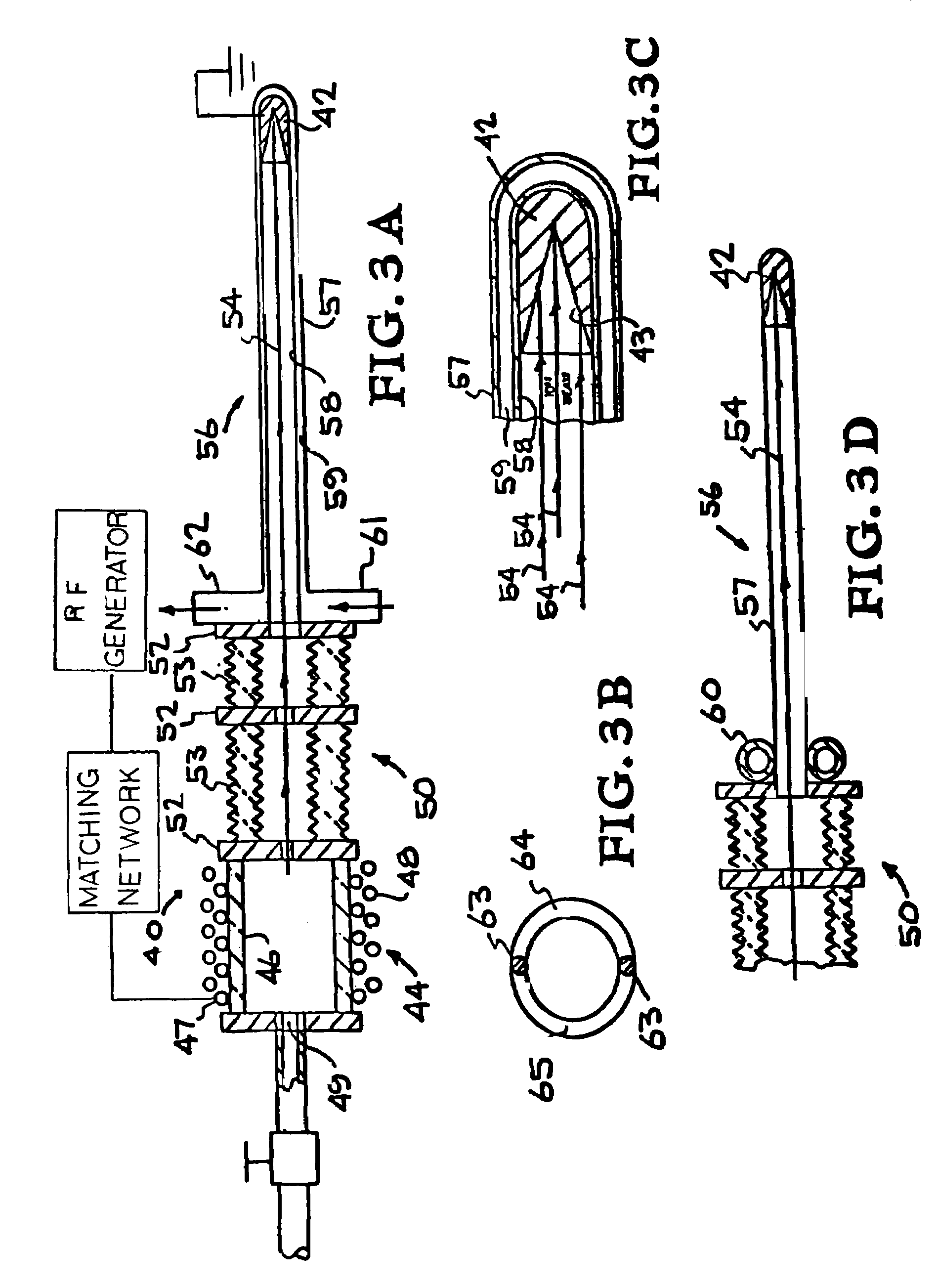
[0013]The invention also includes another miniaturized neutron generator or tube that produces fast neutrons from a D-D reaction which can be used for brachytherapy applications. The tube is again formed of a small RF-driven deuterium ion plasma ion source and has a target to which the ions are accelerated. However, in this embodiment, the target is at the end of a small diameter drift tube, which can be inserted into the body like a catheter. The target also has a tapered or conical shape so that greater surface area is provided for higher neutron flux and lower energy loading.
[0014]The invention includes another embodiment of the neutron generator in which the RF driven ion source is substantially larger in size than the first two embodiments since it is not designed for implantation in the human body. The ion source has a chamber with external RF antenna in which a deuterium tritium, or mixed deuterium / tritium ion plasma is produced. The ions are extracted through a large aperture, typically subdivided into a plurality of small apertures, and accelerated to a neutron generating target which has a tapered or conical target surface. The length of the target surface provides a large neutron generating area to produce a high flux and reduces beam deposition power density.

Problems solved by technology

Neutron yield is limited by the ion source performance and beam size.
The production of neutrons is limited by the beam current and power deposition on the target.
In the conventional neutron tube, the extraction aperture and the target are limited to small areas, and so is the neutron output flux.
The deuterium-on-deuterium (D-D) reaction, with a cross section for production a hundred times lower, has not been able to provide the necessary neutron flux.

Method used


Image

  • Neutron tubes
  • Neutron tubes
  • Neutron tubes

Examples


Embodiment Construction

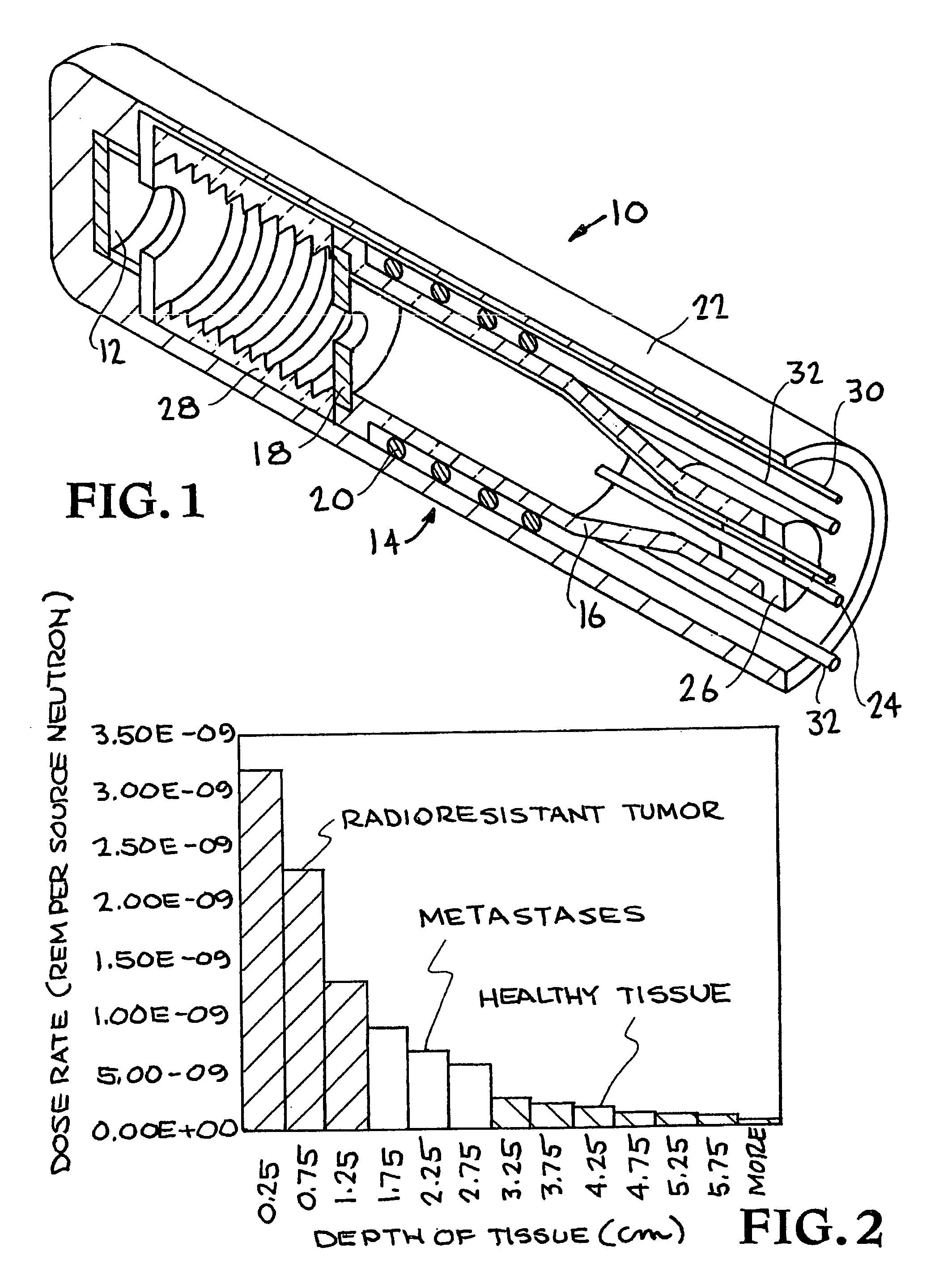
[0021]FIG. 1 shows a miniaturized implantable neutron generator or “mini-neutron-tube”10 of the invention, which has a small neutron generating target (electrode) 12 closely spaced apart from a small plasma ion source 14. Plasma ion source 14 is formed of a quartz (or other material) plasma chamber 16. Ion source 14 and target 12 are mounted in neutron generator housing 22.

[0022]The general principles of plasma ion sources are well known in the art. Ion source 14 includes an RF antenna (induction coil) 20 surrounding (outside) plasma chamber 16 for producing an ion plasma from a gas, typically deuterium, which is introduced into chamber 16 through an inlet 24 which passes through a vacuum plug 26 at an inlet end of chamber 16. Antenna 20 is connected to an external RF power source (not shown) through conductors 32 which pass through the end of generator housing 22. For neutron generation for brachytherapy applications, the plasma produced in ion source 14 is preferably a deuterium i...


PUM


Abstract

A neutron tube or generator is based on a RF driven plasma ion source having a quartz or other chamber surrounded by an external RF antenna. A deuterium or mixed deuterium / tritium (or even just a tritium) plasma is generated in the chamber and D or D / T (or T) ions are extracted from the plasma. A neutron generating target is positioned so that the ion beam is incident thereon and loads the target. Incident ions cause D-D or D-T (or T-T) reactions which generate neutrons. Various embodiments differ primarily in size of the chamber and position and shape of the neutron generating target. Some neutron generators are small enough for implantation in the body. The target may be at the end of a catheter-like drift tube. The target may have a tapered or conical surface to increase target surface area.

Description

RELATED APPLICATIONS[0001]This application claims priority of Provisional Applications Ser. Nos. 60 / 355,576 filed Feb. 6, 2002 and 60 / 356,350 filed Feb. 13, 2002, which are herein incorporated by reference.GOVERNMENT RIGHTS[0002]The United States Government has rights in this invention pursuant to Contract No. DE-AC03-76SF00098 between the United States Department of Energy and the University of California.BACKGROUND OF THE INVENTION[0003]The invention relates generally to neutron tubes, and more specifically to neutron tubes based on plasma ion sources.[0004]Conventional neutron tubes employ a Penning ion source and a single gap extractor. The target is a deuterium or tritium chemical embedded in a molybdenum or tungsten substrate. Neutron yield is limited by the ion source performance and beam size. The production of neutrons is limited by the beam current and power deposition on the target. In the conventional neutron tube, the extraction aperture and the target are limited to sm...

Claims


Application Information

Patent Timeline
Patent Type & Authority Patents(United States)
IPC IPC(8): G21B1/00H05H3/06
CPCH05H3/06Y02E30/10
Inventor LEUNG, KA-NGOLOU, TAK PUIREIJONEN, JANI
Owner RGT UNIV OF CALIFORNIA
Why Eureka
Eureka Blog
Learn More