Rotary cutting tool having a cutting edge formed of veined PCD

A technology of rotating cutting tools and cutting tools, which is applied in the field of rotating cutting tools and can solve the problems of cutting edge weakening

Inactive Publication Date: 2012-05-30
KENNAMETAL INC
View PDF7 Cites 7 Cited by
  • Summary
  • Abstract
  • Description
  • Claims
  • Application Information

AI Technical Summary

Problems solved by technology

Furthermore, due to the removal of PCD material, the resulting cutting edge will be significantly weakened

Method used


Image

  • Rotary cutting tool having a cutting edge formed of veined PCD
  • Rotary cutting tool having a cutting edge formed of veined PCD
  • Rotary cutting tool having a cutting edge formed of veined PCD

Examples


Embodiment Construction

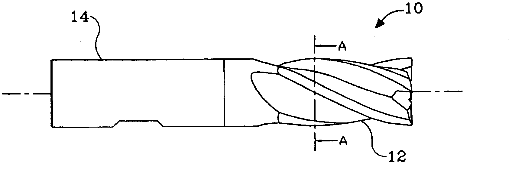
[0029] Figure 4 to Figure 11 Depicts an enlarged cross-sectional view of a textured PCD rotary tool according to the invention, showing different stages of production, the views are along the figure 1 Taken from the same cutting plane indicated by the midline A-A.

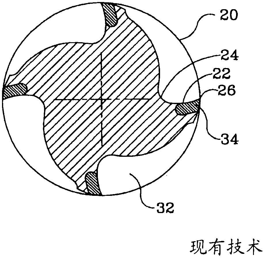
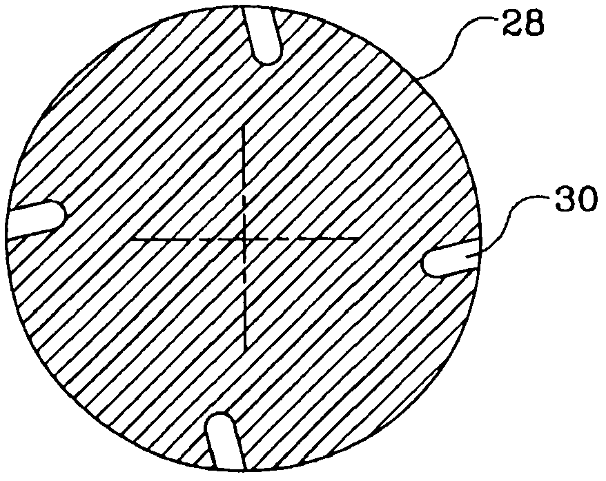
[0030] see Figure 4 and Figure 5 , shows a four flute PCD rotary cutter 40 and corresponding blank 42 manufactured according to a first embodiment of the present invention. As seen in a section perpendicular to the tool axis, the face of the tooth is divided into two parts: a first concave portion 44 adjacent to the cutting edge 46 (forming a first curved surface), and adjacent to the tooth root 50. And a second recessed portion 48 adjoining the first portion 44 (constituting a second curved surface). The TC blank 42 is provided with grooves 52 formed with a leading face 54 corresponding to the shape of the first recessed portion 44 of the cutter 40 . In some embodiments, the first recessed portion 44 is s...


PUM


Abstract

A rotary cutting tool (40) formed from a blank (42) having at least one tooth (58) including a root (50) and a cutting edge (46) formed of veined PCD, wherein the tooth face as viewed in a cross-section perpendicular to an axis of the cutting tool includes a first curved surface (44, 64) proximate the cutting edge, and a second curved surface (48, 68) proximate the root (50) and the first curved surface. For each cutting edge, the blank is provided with a respective groove (52) having a leading surface (54) that corresponds in shape to the first curved surface of the respective tooth.

Description

technical field [0001] The present invention relates to rotary cutting tools, and more particularly to rotary cutting tools having a plurality of textured polycrystalline diamond cutting edges and processes for their manufacture. Background technique [0002] It is known in the field of cutting tools to use polycrystalline diamond (PCD) or cubic boron nitride (CBN) compacted and sintered onto a tungsten carbide (TC) blank. For the sake of brevity, PCD and CBN or other diamond-like materials will hereafter be defined as the term PCD. [0003] US Patent 5,070,748 to Packer describes the process of forming such a rotary tool by forming a rotary tool blank having cemented tungsten carbide; at least one pair of longitudinally extending grooves are formed in one outer surface of the blank filling the grooves with diamond-like material; incorporating the diamond-like material into the grooves in the rotary tool blank under sufficient heat and pressure to form polycrystalline diamo...

Claims


Application Information

Patent Timeline
Patent Type & Authority Applications(China)
IPC IPC(8): B23C5/10B23P15/34
CPCB23C2210/282B23C2226/315B23C2226/125B23C5/10Y10T407/1946
Inventor V·沃洛赫L·沙里弗克
Owner KENNAMETAL INC
Why Eureka
Try Eureka