Main brake cylinder and method for operating a main brake cylinder

A master brake cylinder, working technology, applied in the direction of braking action starting device, brake transmission device, brake, etc.

Inactive Publication Date: 2012-05-30
ROBERT BOSCH GMBH
View PDF9 Cites 10 Cited by
  • Summary
  • Abstract
  • Description
  • Claims
  • Application Information

AI Technical Summary

Problems solved by technology

But this implies the following danger: when the external force fails, there is no longer a mechanical coupling between the brake pedal and the wheel brake, or the mechanical coupling can only be achieved after overcoming the idle travel of the brake pedal, so that there is no the possibility of emergency maneuvers by the operator without apparent irritating reaction

Method used


Image

  • Main brake cylinder and method for operating a main brake cylinder
  • Main brake cylinder and method for operating a main brake cylinder
  • Main brake cylinder and method for operating a main brake cylinder

Examples


Embodiment Construction

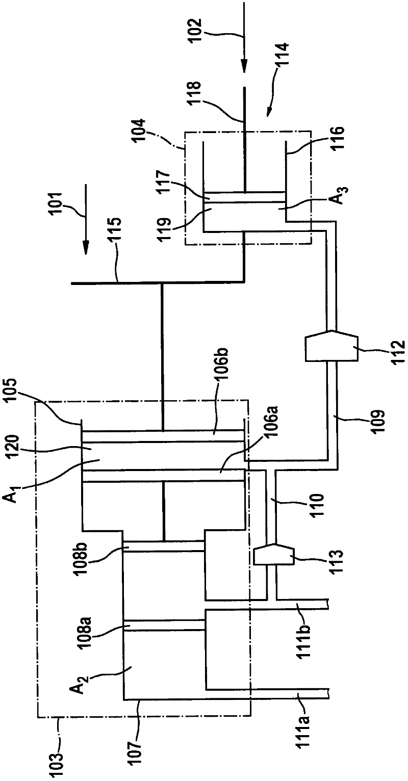
[0034] In a preferred embodiment, the overall brake system consists of a conventional hydraulic part (including, for example, ESP, ABS components) and a further part. For the sake of example, it is assumed that a further partial contribution to the braking effect of the overall braking system is due to the regenerative braking system and is produced by the generator torque. The conventional part of the braking system includes an actuating device 114 via which the human power of the driver 102 can be introduced into the braking system. This driver effort can be combined with an auxiliary force 101 , for example from a controllable brake booster, at a coupling element 115 , for example at a reaction disc. The controllable brake booster can be both an electromechanical brake booster and a controllable vacuum brake booster with electrically actuated valves, but other embodiments are also conceivable. In a conventional hydraulic brake system, the coupling element 115 transmits the...


PUM


Abstract

The invention relates to a method and a device as part of a complete brake system, that is, a brake system comprising a conventional part and a further part, such as a recuperative part, by means of which volume displacements of brake fluid are possible. The method according to the invention and the device according to the invention are used particularly if the pressure conditions in the hydraulic part of the brake system are adapted by the controllable braking force amplifier to a change in the additional braking effect of the further part of the brake system. A blending of the braking effects of the different brake systems into a constant total braking effect is thus accomplished, even if the proportion of the individual brake systems in the total braking effect change. Such a pressure adaptation by the braking force amplifier is generally accompanied by a reaction on the brake pedal, particularly a displacement thereof. The pressure adaptation can take place by means of the volume displacements between at least one hydraulic braking circuit, a compensating chamber, and either an input chamber in the brake pedal or a hydraulic reservoir, without the driver realizing the same at the brake pedal due to a change in position, and thus perceiving the same as disturbing. The method can be used, for example, for vehicles wherein a delay in braking is brought about by operating an electric machine as a generator for generating electricity, and additionally comprising a conventional hydraulic brake system as a further brake system or backup brake system.

Description

technical field [0001] The invention relates to a master brake cylinder and a method for operating the master brake cylinder. Background technique [0002] In hydraulic braking systems of motor vehicles, the brake pedal is in most cases actuated by the driver and, if necessary, mechanically moves the piston in the master brake cylinder with the support of a brake booster, the hydraulic The outlet of the brake cylinder is connected. As a result, brake fluid is fed into the hydraulic system (for example ESP or ABS) and introduced into the wheel brake cylinders. Here, the input volume increases the brake pressure and produces a braking effect by pressing the brake pads against the brake disc. [0003] In vehicles provided with an electric motor for driving the motor vehicle, the electric motor can be used as a generator, for example to charge a battery, in driving situations in which the electric motor is not used as a drive. Running the electric motor as a generator creates...

Claims


Application Information

Patent Timeline
Patent Type & Authority Applications(China)
IPC IPC(8): B60T11/224B60T13/68
CPCB60T1/10B60T11/224B60T8/38B60T13/686B60T7/042
Inventor D·曼科普夫
Owner ROBERT BOSCH GMBH
Why Eureka
Try Eureka