
Method For Correcting The Temperature Of A Force Measuring Apparatus And Force Measuring Apparatus

A technology for measuring equipment and temperature correction, applied in the direction of weighing equipment testing/calibration, weighing equipment using electromagnetic balance, weighing equipment using elastically deformable parts, etc., can solve non-representative, dependent, temperature sensor installation and adjustment problems, to achieve the effect of simple design, low-cost design, and accurate temperature compensation

Active Publication Date: 2012-05-30
METTLER TOLEDO INC
View PDF8 Cites 9 Cited by
  • Summary
  • Abstract
  • Description
  • Claims
  • Application Information

AI Technical Summary

Problems solved by technology

However, the installation and adjustment of temperature sensors is still fraught with challenges
Furthermore, for the correction of the temperature in relation to the magnetic field, the measured values ​​may not be representative, since the latter mainly depends on the temperature of the permanent magnet and only secondarily on the temperature of the coil

Method used


Image

  • Method For Correcting The Temperature Of A Force Measuring Apparatus And Force Measuring Apparatus
  • Method For Correcting The Temperature Of A Force Measuring Apparatus And Force Measuring Apparatus
  • Method For Correcting The Temperature Of A Force Measuring Apparatus And Force Measuring Apparatus

Examples


Embodiment Construction

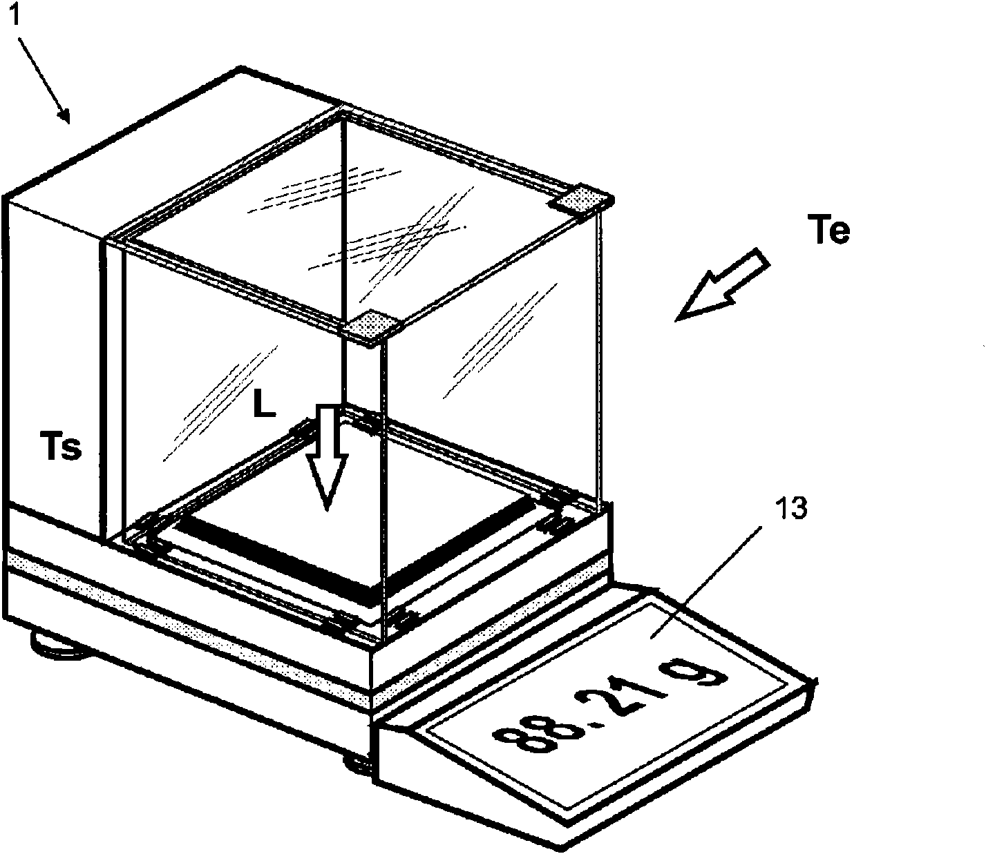
[0065] figure 1 A balance 1 is depicted as a typical example, wherein a load L acting on the balance 1 is symbolically indicated. In response, a compensating force F acting against the input load L is developed. Also symbolically indicated is the ambient temperature Te, which acts on the balance from the outside and has a significant influence on the accuracy and stability of the measurement. On the one hand, the measured value determined by the balance varies as a function of the load L, but it also varies depending on the ambient temperature Te and in response to the effect of the system temperature Ts acting inside the force measuring device.

[0066] As will be described in the following paragraphs, the system temperature Ts may deviate from the ambient temperature Te for various reasons. For example, during the generation of the compensating force, power is dissipated in the interior space of the balance, which causes an increase in the temperature Ts of the system. Ho...


PUM


Abstract

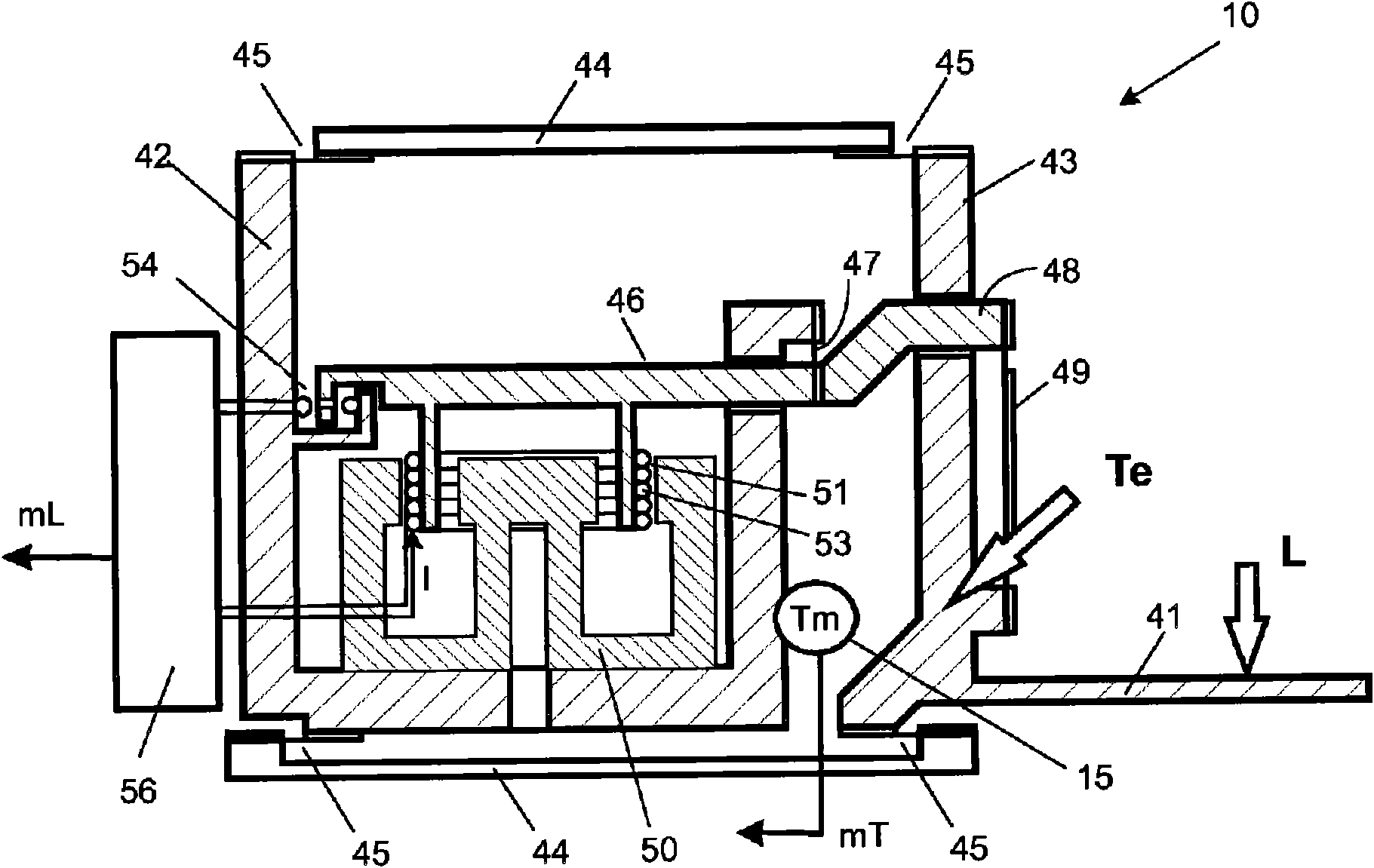
The invention relates to a method for correcting the temperature of a force measuring apparatus (1) that is based on the principle of electromagnetic force compensation, particularly a scale, during normal measuring operation, comprising the following steps: generating an electric force measurement signal (mL) corresponding to a force that is acting on the force measuring apparatus using a load cell (10); generating an electric temperature measurement signal (mT) using a temperature sensor (15), which is disposed at a distance from the heat-generating components of the force measuring apparatus (1), said signal corresponding to the ambient temperature (Te) acting on the force measuring apparatus; processing the force measurement signal (mL) on the basis of the temperature measurement signal (mT) and the force measurement signal(mL) into a temperature-corrected output signal (mLc); transmitting the output signal (mLc) to a display unit (13) and / or a further processing unit (14). To this end, during the processing step based on the force measurement signal (mL) and / or the temperature measurement signal (mt), at least one corrective parameter (CP) used to correct the output signal (mLc) is calculated using a thermodynamic model, said parameter characterizing a temperature difference (dTr, dT1, dT2) that exists between a system temperature (Ts, Ts1, Ts2) and the ambient temperature (Te), or between a first system temperature (Ts1) and a second system temperature (Ts2).

Description

technical field [0001] The invention relates to a method for correcting temperature-dependent errors in a force-measuring device, in particular a balance, and a force-measuring device possessing the necessary properties. Background technique [0002] A force measuring device usually comprises different functional parts, for example a force receiver, a force transmission mechanism, a force measuring cell and sometimes devices for processing the measurement signal. The force to be measured is received by the force receiver and transmitted to the force-measuring unit via the force transmission mechanism. The force measurement unit converts the input force into an electrical measurement signal corresponding to the force acting on the force measurement device. [0003] Similarly, in the case of a balance, the gravitational force of the weighing object represents an input force, the so-called weighing load, acting on a force receiver in the form of a weighing pan. This force inp...

Claims


Application Information

Patent Timeline
IPC IPC(8): G01G3/18G01G7/04G01G23/01G16Z99/00
CPCG01G7/04G01G3/18G01G23/01G16Z99/00G06F17/40G01G23/48
Inventor T·克佩尔D·雷伯
Owner METTLER TOLEDO INC
Learn More