Heat recycling backflow welding machine

A reflow soldering machine and heat energy technology, applied in electric heating devices, welding equipment, assembling printed circuits with electrical components, etc., can solve the problems of affecting PCB cooling, power consumption, energy waste, etc., to reduce power consumption and simple structure. , Reasonable design effect

Inactive Publication Date: 2012-06-06
XIAN ZHONGKEMAITE ELECTRONICS TECH EQUIP
View PDF7 Cites 12 Cited by
  • Summary
  • Abstract
  • Description
  • Claims
  • Application Information

AI Technical Summary

Problems solved by technology

Generally, the reflow soldering machine is divided into three areas: preheating zone, welding zone and cooling zone. The temperature in the soldering temperature zone is the highest in each temperature zone of the reflow soldering machine, and the physical distance between the soldering zone and the cooling zone is relatively close, only 100mm-200mm , the hot and cold air spread to each other's temperature zone, which not only affects the cooling of the PCB, but also wastes energy. At the same time, the large temperature difference between the soldering zone and the cooling zone will consume a lot of power, which has not been paid attention to by the industry.

Method used


Image

  • Heat recycling backflow welding machine
  • Heat recycling backflow welding machine

Examples


Embodiment Construction

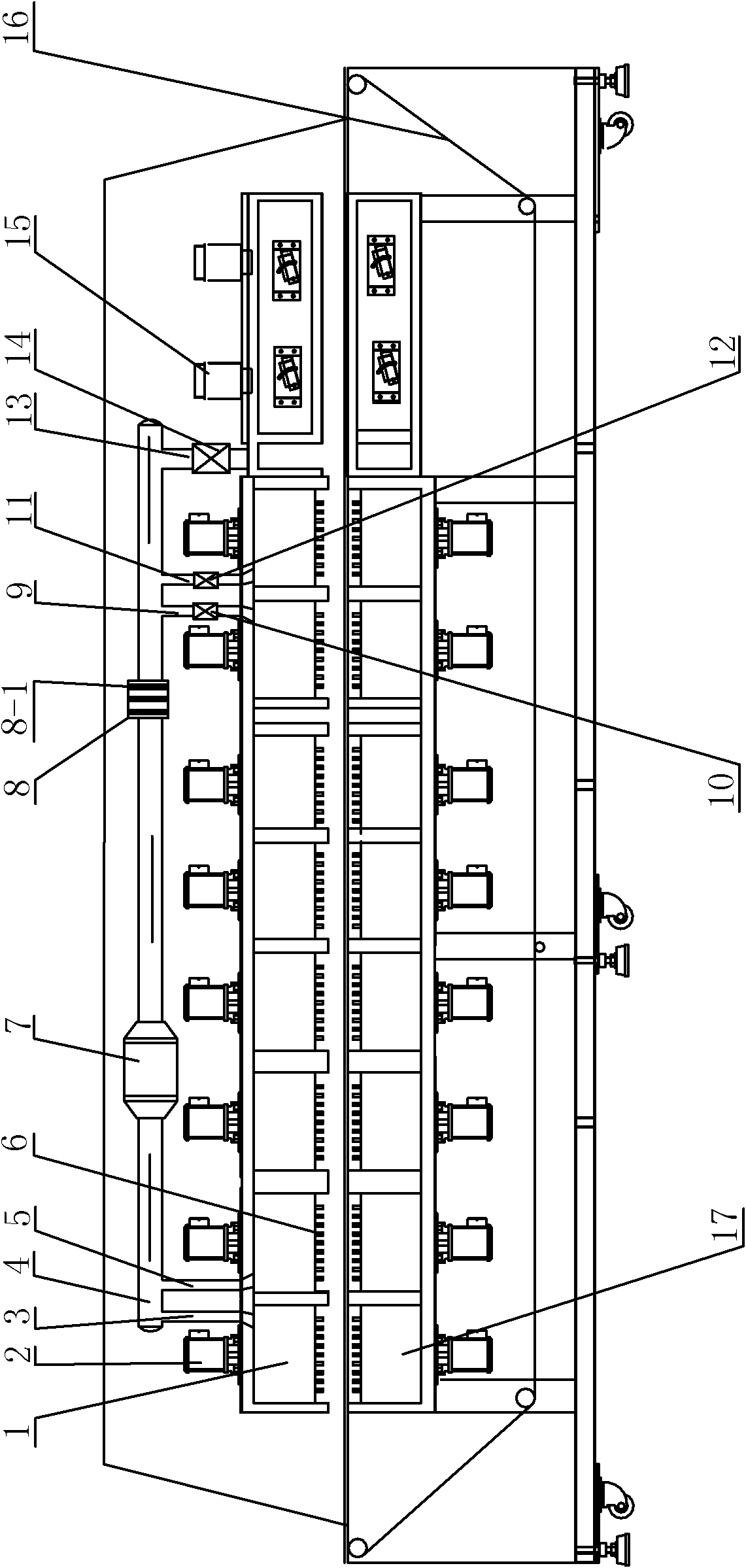
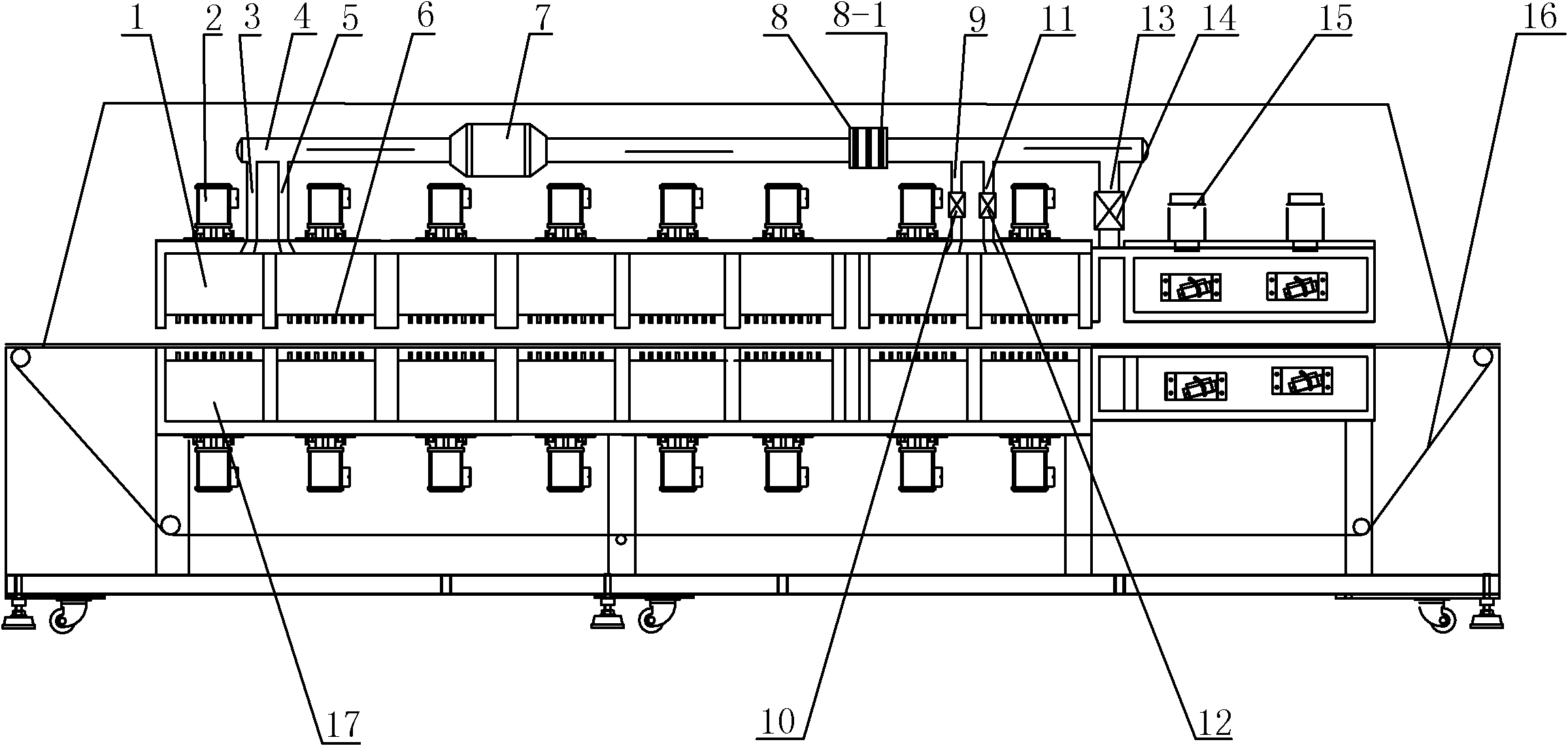
[0022] Such as figure 1 The heat recycling reflow soldering machine shown includes a preheating zone, a welding zone, and a cooling zone arranged sequentially from left to right, and is used to drive the PCB through the preheating zone, the welding zone, and the cooling zone in sequence. The PCB conveying system in the zone also includes a thermal energy recycling system arranged above the preheating zone and the welding zone, and the thermal energy recycling system includes a preheating zone air inlet channel 1 and a preheating zone air inlet channel 2 5. Heat recovery channel 4, pipeline fan 7, filter 8, welding zone air outlet channel one 9, welding zone air outlet channel two 11 and cold and hot combined air outlet channel 13, the left end of the heat recovery channel 4 is connected to the preheating zone The first air inlet passage 3 and the second air inlet passage 5 in the preheating area are all connected, the right end of the heat recovery passage 4 is connected with ...


PUM


Abstract

The invention discloses a heat recycling backflow welding machine comprising a pre-heating zone, a welding zone and a cooling zone which are sequentially distributed from left to right, and a printed circuit board (PCB) conveying system which is used for driving a PCB to sequentially pass through the pre-heating zone, the welding zone and the cooling zone; the heat recycling backflow welding machine also comprises a heat recycling system which is arranged above the pre-heating zone and the welding zone; the heat recycling system comprises a pre-heating zone air inlet channel I, a pre-heating zone air inlet channel II, a heat recovery channel, a pipeline fan, a filter, a welding zone air outlet channel I, a welding zone air outlet channel II and a cold and heat integrated air outlet channel; the left end of the heat recovery channel is communicated with the pre-heating zone air inlet channel I and the pre-heating zone air inlet channel II, and the right end of the heat recovery channel is communicated with the cold and heat integrated air outlet channel; the pipeline fan and the filter are arranged in the middle part of the heat recovery channel; and the welding zone air outlet channel I and the welding zone air outlet channel II are arranged on the heat recovery channel. The heat recycling backflow welding machine can greatly reduce the electricity consumption when the backflow welding machine is used.

Description

technical field [0001] The invention relates to a reflow soldering machine, in particular to a thermal energy recycling reflow soldering machine capable of reducing electric energy consumption during the use of the reflow soldering machine. Background technique [0002] As human society enters the low-carbon era, energy conservation and emission reduction are important tasks in all aspects of society, especially in production. Reflow soldering machines are high energy-consuming equipment, and energy saving of reflow soldering machines is extremely important to manufacturers. At present, the conventional energy-saving measures for reflow soldering machines are to do a good job of heat preservation for the furnace body of the reflow soldering machine. Generally, the reflow soldering machine is divided into three areas: preheating zone, welding zone and cooling zone. The temperature in the soldering temperature zone is the highest in each temperature zone of the reflow solderin...

Claims


Application Information

Patent Timeline
Patent Type & Authority Applications(China)
IPC IPC(8): B23K3/08B23K3/00B23K3/04H05K3/34
Inventor 张国琦曹捷梁保华
Owner XIAN ZHONGKEMAITE ELECTRONICS TECH EQUIP
Why Eureka
Try Eureka