
Cooling system for automobile engine

A technology of automobile engine and cooling system, which is applied in the direction of engine cooling, engine components, machine/engine, etc. It can solve the problems of aggravated engine body vibration, insufficiently compact engine structure, and large engine vibration and noise, so as to improve the cooling effect and shorten the cooling time. Warm-up time, the effect of reducing fuel consumption

Inactive Publication Date: 2012-06-06
SAIC-GM-WULING AUTOMOBILE CO LTD
View PDF5 Cites 16 Cited by
  • Summary
  • Abstract
  • Description
  • Claims
  • Application Information

AI Technical Summary

Problems solved by technology

In this way, the intake side of the engine will be relatively crowded in layout, while the exhaust side only has the exhaust manifold, and the engine structure is relatively not compact enough.
And the parts of the cooling system are far away from the center of motion of the engine, aggravating the vibration of the engine body and causing excessive vibration and noise of the engine

Method used


Image

  • Cooling system for automobile engine
  • Cooling system for automobile engine
  • Cooling system for automobile engine

Examples


Embodiment Construction

[0027] The present invention will be further described below in conjunction with the accompanying drawings.

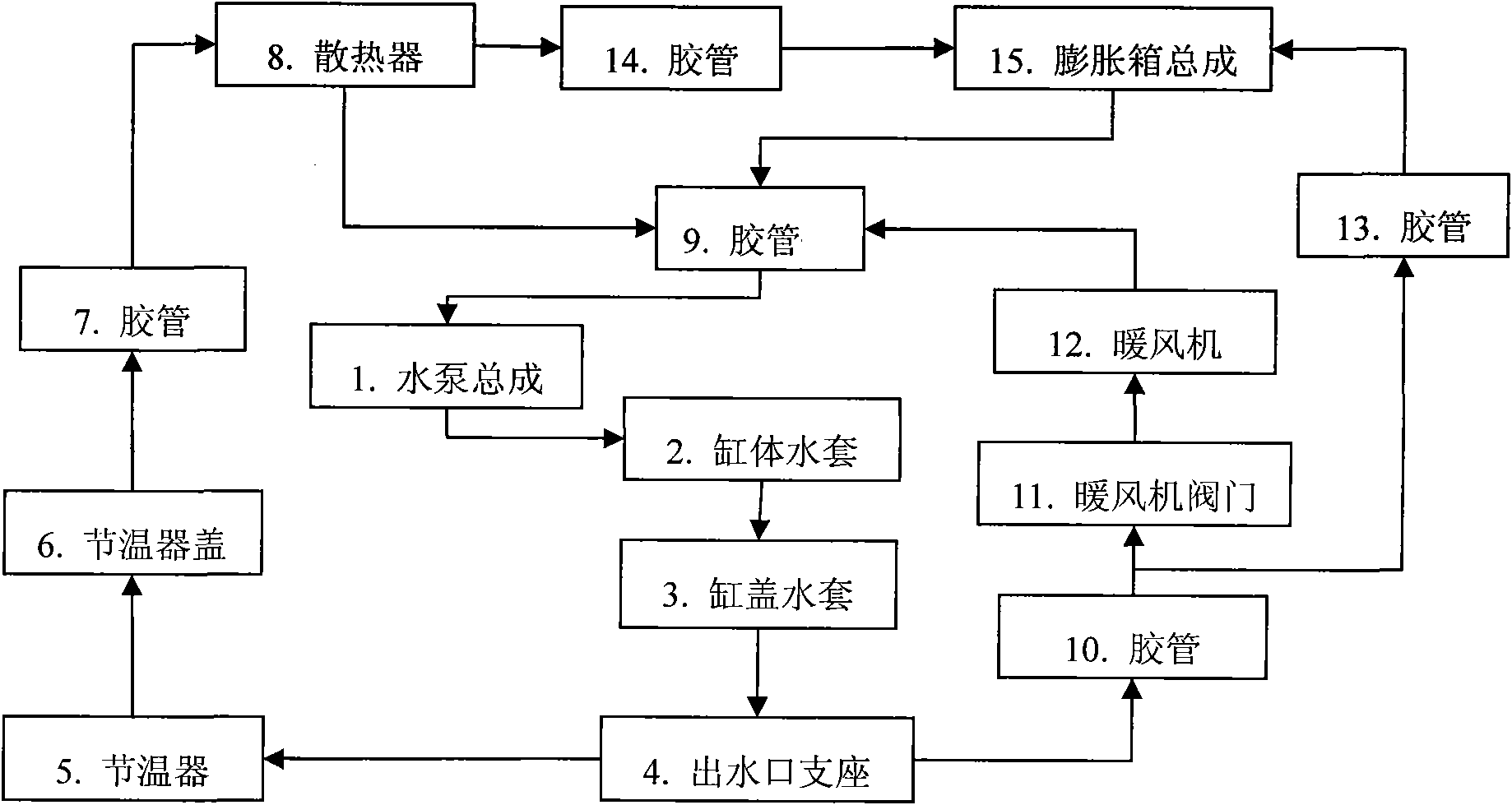
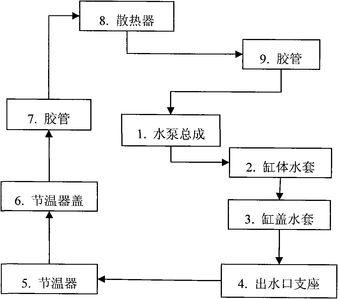
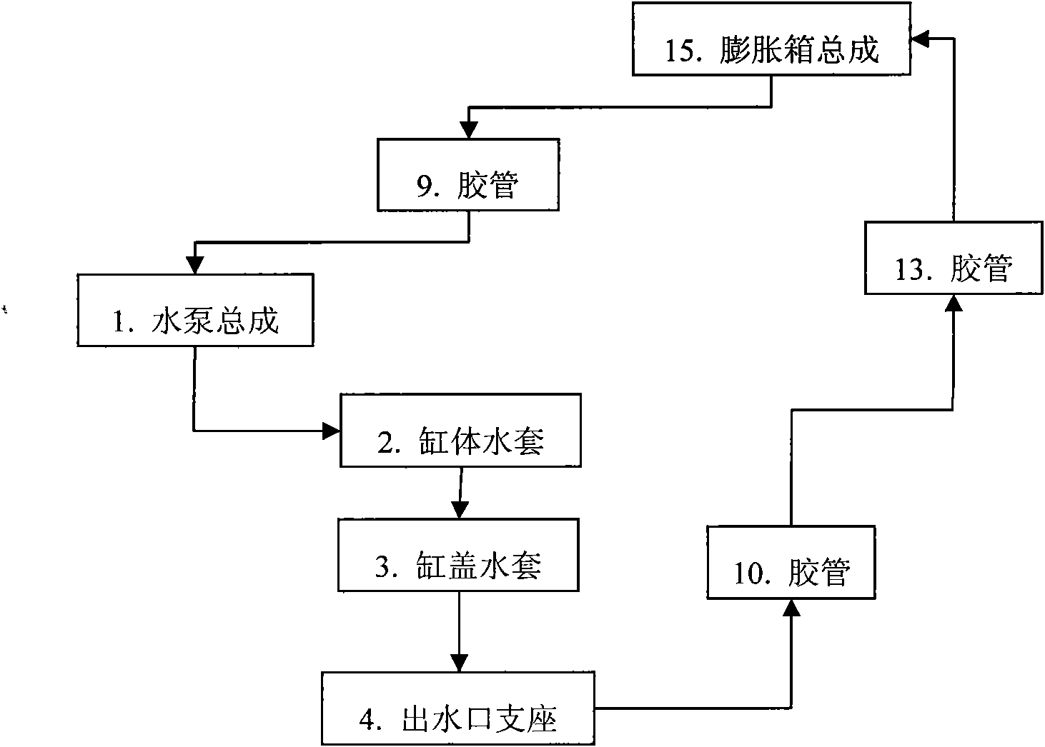
[0028] As is well known to those skilled in the art, Figure 1 to Figure 4 The components that are not directly connected are mainly connected by rubber tubes, and the arrows in the figure indicate the flow direction of the coolant between the components.

[0029] refer to figure 1 and figure 2 The large circulation loop in the automobile engine cooling system of the present invention is illustrated. The automobile engine cooling system includes a water pump assembly 1, a cylinder body water jacket 2, a cylinder head water jacket 3, a water outlet support 4, a radiator 8 and an expansion tank assembly 15; the water outlet support 4 is arranged on the cylinder The rear end of the cover 16 is used to collect the high-temperature coolant flowing out from the engine cylinder head water jacket 3; The water inlet is connected, and the water outlet of the water outlet su...


PUM


Abstract

The invention relates to a cooling system for an automobile engine. The cooling system comprises a water pump, a cylinder body water sleeve, a cylinder cover water sleeve, a water outlet support, a heat radiator and an expansion box assembly. The water outlet support is arranged at the back end of the water outlet support for collecting a cooling liquid which flows from the cylinder cover water cover. The water outlet of the water pump is connected with the water inlet of the water outlet support by the cylinder body water sleeve and the cylinder cover water sleeve. The water outlet of the water outlet support is connected with the water inlet of the water pump by the heat radiator so that a closed loop is formed. The water inlet of the expansion box assembly is connected with the heat radiator and the water outlet of the expansion box assembly is connected with the water inlet of the water pump. Furthermore, the water inlet of the expansion box assembly is connected with the water outlet of the water outlet support. Moreover, the cooling system disclosed by the invention further comprises a heater. The cooling system for the automobile engine disclosed by the invention not only has reasonable arrangement in a structure of the entire automobile cooling system, but also is convenient to exhaust. And the engine can be rapidly warmed up in cold boot by two small circular loops.

Description

【Technical field】 [0001] The invention relates to the field of engines, in particular to an automobile engine cooling system. 【Background technique】 [0002] At present, most automobile engines use forced circulation water cooling system. "Automobile Structure" (2nd edition, edited by Guan Wenda of Jilin University, Mechanical Industry Press) discloses a water cooling system. Under the action of the water pump, the coolant flows through the water jacket of the cylinder body and the water jacket of the cylinder head to absorb heat, and then flows into the radiator along the water pipe. The temperature of the high-temperature coolant drops after being dissipated by the radiator, and is pressed into the water jacket of the engine by the water pump again, so that the heat of the engine is taken away by the cycle in this way. A thermostat is usually installed at the water inlet of the water pump or the water outlet of the cylinder head. When the temperature of the engine coola...

Claims


Application Information

Patent Timeline
Patent Type & Authority Applications(China)
IPC IPC(8): F01P3/20F01P11/00F01P7/16F01P5/10B60H1/02
Inventor 刘高领张帆方明壮
Owner SAIC-GM-WULING AUTOMOBILE CO LTD
Learn More