Control system and control method of fan

A fan control and fan technology, applied in pump control, sustainable buildings, instruments, etc., can solve problems such as rising, fan acceleration, system temperature can not be in a stable state, etc., to achieve the effect of reducing fan noise and saving energy consumption

Inactive Publication Date: 2012-06-06
HONG FU JIN PRECISION IND (SHENZHEN) CO LTD +1
View PDF9 Cites 20 Cited by
  • Summary
  • Abstract
  • Description
  • Claims
  • Application Information

AI Technical Summary

Problems solved by technology

As a result, the fan has to slow down immediately after accelerating, resulting in unnecessary power consumption and noise generation
And when the temperature of a certain area exceeds the threshold value, the fan speeds up to dissipate heat only for this area, and it is easy to dissipate the heat to other areas. In steady state, resulting in unnecessary fan acceleration or deceleration, resulting in unnecessary power consumption and noise

Method used


Image

  • Control system and control method of fan
  • Control system and control method of fan
  • Control system and control method of fan

Examples


Embodiment Construction

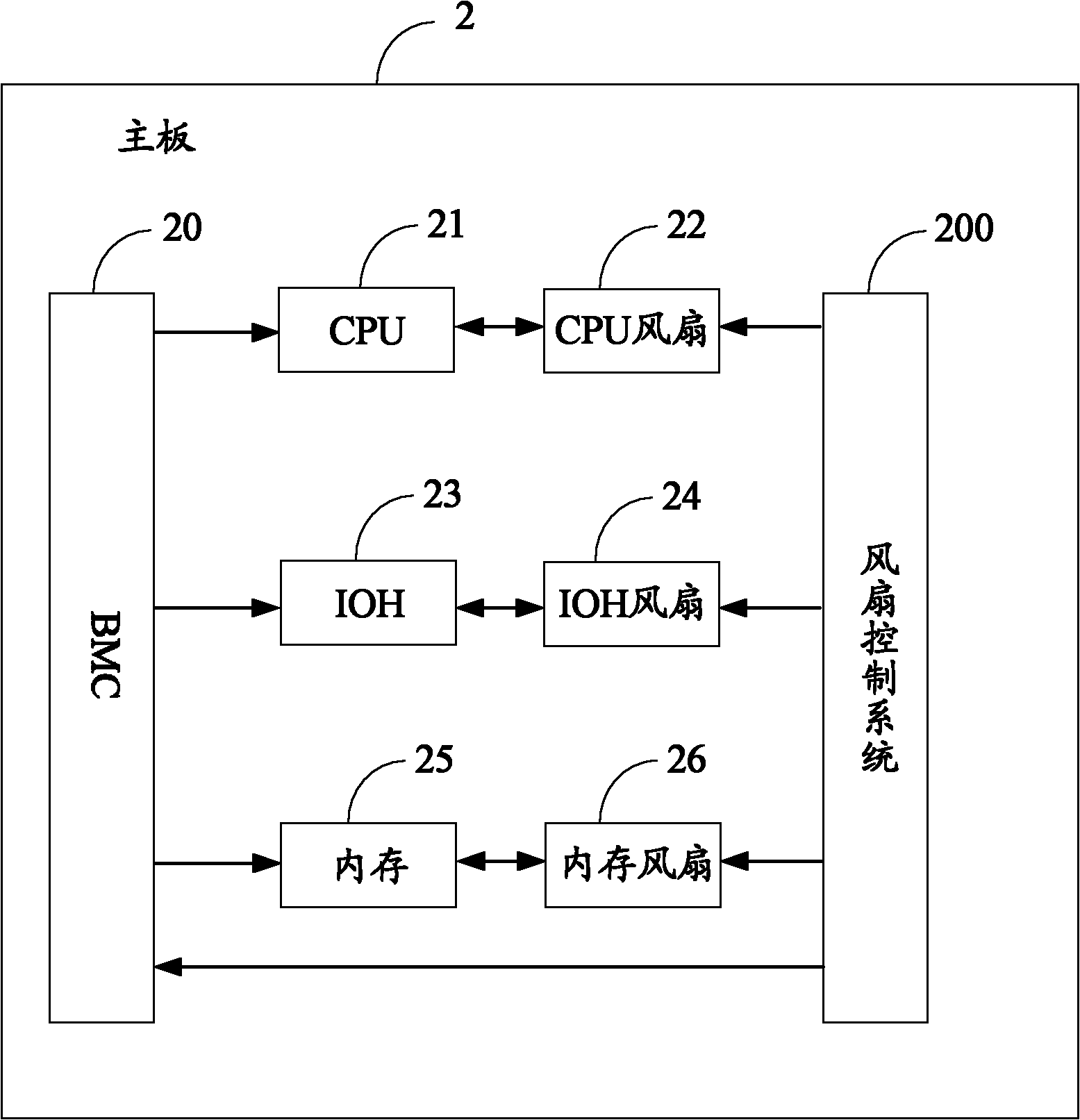
[0013] Such as figure 1 Shown is the application environment diagram of the preferred embodiment of the fan control system of the present invention. Wherein, the fan control system 200 runs on the mainboard 2, and the mainboard 2 also includes a baseboard management controller (Baseboard Management Controller, BMC) 20, a CPU 21, a CPU fan 22, an input and output hub (Input Output Hub, IOH) 23, IOH fan 24, memory 25 and memory fan 26.

[0014] The BMC 20 is connected to the CPU 21, the IOH 23 and the memory 25, and the BMC 20 is used to read the temperature of the CPU 21, the temperature of the IOH 23 and the temperature of the memory 25 in real time. Specifically, in the A temperature sensor (not shown) is installed on or around the CPU 21, IOH 23 and memory 25, and the BMC 20 can read the temperature of the CPU 21, the temperature of the IOH 23 and the temperature of the memory 25 through the temperature sensor. temperature. Wherein, the IOH 23 is a north bridge.

[0015]...


PUM


Abstract

The invention discloses a control system and a control method for a fan. The control method comprises the following steps of: setting a tachometer of a CPU (Central Processing Unit) fan, a tachometer of an IOH (Input Output Hub) fan and a tachometer of a memory fan; reading the temperature of the IOH; judging whether the rotating speed of the IOH fan is required to be adjusted or not; reading corresponding rotating speed from the tachometer of the IOH fan according to the read temperature to adjust the rotating speed of the IOH fan and taking the temperature as the temperature of the CPU and the temperature of the memory; reading corresponding rotating speed from the tachometer of the CPU fan according to the temperature to adjust the rotating speed of the CPU fan; reading corresponding rotating speed from the tachometer of the memory fan to adjust the rotating speed of the memory fan; respectively reading the temperature of the CPU, the temperature of the IOH and the temperature of the memory; and respectively adjusting the rotating speed of the CPU fan, the rotating speed of the IOH fan and the rotating speed of the memory fan. According to the control system and the control method disclosed by the invention, repeated adjustment for the fans near a threshold value can be avoided, energy consumption is reduced and noises of the fans are reduced.

Description

technical field [0001] The invention relates to a fan control system and method. Background technique [0002] During the operation of the fan in the computer, when the temperature is close to the threshold, the following phenomenon will occur: when the temperature exceeds the threshold, the fan will speed up, and when the temperature is lower than the threshold, the fan will immediately slow down in a short time. As a result, the fan speeds up immediately but immediately slows down in a short period of time, resulting in unnecessary power consumption and noise generation. And when the temperature of a certain area exceeds the threshold value, the fan speeds up to dissipate heat only for this area, and it is easy to dissipate the heat to other areas. In a steady state, unnecessary fan acceleration or deceleration occurs, resulting in unnecessary power consumption and noise. Contents of the invention [0003] In view of the above, it is necessary to provide a fan control ...

Claims


Application Information

Patent Timeline
Patent Type & Authority Applications(China)
IPC IPC(8): F04D27/00G06F1/20
CPCY02B60/1275Y02D10/00
Inventor 王新富
Owner HONG FU JIN PRECISION IND (SHENZHEN) CO LTD
Why Eureka
Try Eureka