Air supersonic-velocity condensation and cyclone separation spray pipe

A swirl separation and supersonic technology, applied in the direction of gas fuel, separation method, dispersed particle separation, etc., can solve the problems of large fluid flow loss, increased processing capacity, large pressure loss, etc., to strengthen and stabilize swirl, improve Separation efficiency and high swirling ability

Inactive Publication Date: 2012-06-13
文闯
View PDF28 Cites 7 Cited by
  • Summary
  • Abstract
  • Description
  • Claims
  • Application Information

AI Technical Summary

Problems solved by technology

Chinese patent ZL 200410074338.8 adopts the swirl device installed in the supersonic section, which is easy to generate shock waves; patent application No. 200810224499.9 and patent application No. 200910093744.1 install the swirl blades in the high-speed flow area, and the fluid flow loss is large; patent ZL200610043158.2, application No. 200610105199.X and ZL 200910023458.8 have the problem that the rotating gas is prone to vortex dissipation; the patent ZL200810011258.6 adopts the form of fluid entering the separation device tangentially, the pressure loss is large, and the total pressure recovery efficiency is reduced; the application No. 200910081813.7 The patented structure is similar to the "TwisterII" separator, but the centering of the vortex control body is more difficult, and it is difficult to ensure the coaxial swirl flow; Xi'an Jiaotong University's application number 200910024347.9 patent has a shock wave compression zone after the supersonic section to decelerate the supersonic compression to subsonic speed, but the droplets are prone to re-volatility in the subsonic region, which reduces the separation efficiency of the separator; the essence of the patent application number 200910084262.X is to connect multiple supersonic separation tubes in parallel to increase the processing capacity; the patent application number 201010597341.3 A supersonic cyclone separator with multiple outlets is designed, which increases the amount of gas entrainment at the liquid outlet, and multiple outlets are also difficult to apply on site

Method used


Image

  • Air supersonic-velocity condensation and cyclone separation spray pipe
  • Air supersonic-velocity condensation and cyclone separation spray pipe
  • Air supersonic-velocity condensation and cyclone separation spray pipe

Examples


Embodiment Construction

[0024] The structural features and working principles of the present invention will be further described below in conjunction with the accompanying drawings.

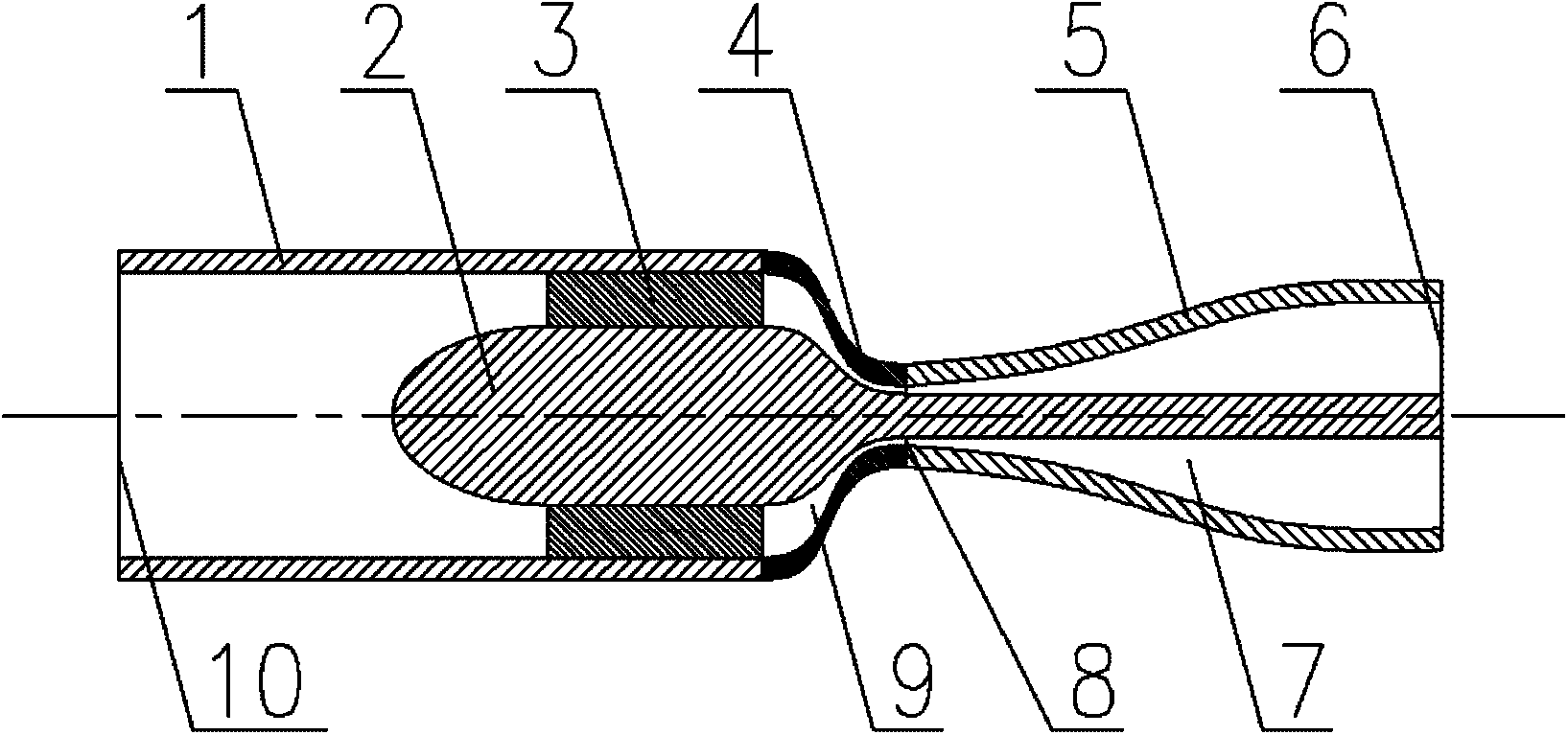
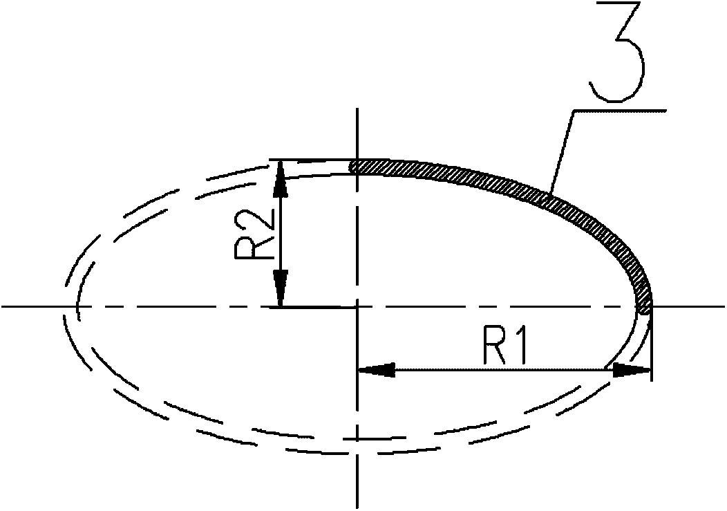
[0025] Such as figure 1 , figure 2 with image 3 As shown, the present invention is mainly composed of a straight pipe section 1, a central body 2, swirl vanes 3, a contraction section 4, an expansion section 5, an inlet 10 and an outlet 6; - Expansion of the nozzle to form a subsonic contraction channel 9, a throat 8 and a supersonic expansion channel 7; the upper end of the swirl vane 3 is fixedly connected to the inner wall of the straight pipe section 1, and the lower end is fixedly connected to the surface of the central body 2.

[0026] Such as figure 1 As shown, the shrinkage section 4 of the present invention is a tapered structure, and its contour curve is designed according to the following curve equation:

[0027] D x = D cr ...


PUM


Abstract

The invention relates to an air supersonic-velocity condensation and cyclone separation spray pipe. The air supersonic-velocity condensation and cyclone separation spray pipe mainly comprises a central body, a cyclone blade, a contraction section and an expansion section, and is mainly applied to air purification, particularly the field of natural gas dehydration and heavy hydrocarbon separation.The cyclone blade is designed by an elliptical blade method, and can effectively strength cyclone; the central body can effectively reduce eddy dissipation, and the curve of the contraction section can guarantee that the velocity of air flow can be stably increased to sound velocity; the contraction section has a gradually expanded structure, and simple linear design in the conventional device isabandoned; and the curve design can avoid the influence of expansion waves, and the spray pipe is good in aerodynamic performance. In the spray pipe, the velocity of the air flow is supersonic velocity, the residence time is very short, hydrate is avoided, and chemical agents and relative recovery systems are not needed to be added. Moreover, the spray pipe has the advantages of supporting unmanned operation, along with no movement component, compact structure, small occupied space and the like, is particularly suitable for development of oil and gas fields of boundary and desert, and offshore oil and gas fields, and has a wide application range.

Description

Technical field: [0001] The invention relates to a gas supersonic condensation and cyclone separation nozzle, which is mainly used in gas purification, especially in the fields of natural gas dehydration, heavy hydrocarbon separation and the like. Background technique: [0002] Traditional gas dehydration technologies mainly include cooling method, absorption method, adsorption method and membrane separation method. The cooling method uses the principle that the water content of the gas decreases as the temperature drops or the pressure increases to achieve gas dehydration, mainly including direct cooling method, pressurized cooling method, expansion refrigeration method and vapor compression refrigeration method. In order to prevent the formation of hydrates, the system needs to be heated or hydrate inhibitors and corresponding recovery systems need to be added. The absorption method uses the principle of different solubility of gas in liquid to realize gas dehydration. Th...

Claims


Application Information

Patent Timeline
Patent Type & Authority Applications(China)
IPC IPC(8): B01D45/16C10L3/10
Inventor 文闯曹学文杨燕
Owner 文闯
Why Eureka
Try Eureka