Two-part type immersion type water opening electromagnetic cyclone device and supporting device thereof
A swirl device and immersion technology, which is applied in the field of electromagnetic swirl device and its support device of the two-petal submerged nozzle, can solve the problems of inconvenient continuous casting operation on site, interruption of swirl effect, low efficiency of magnetic field, etc., and guarantees Smooth operation, control of molten steel flow, and high magnetic field utilization
- Summary
- Abstract
- Description
- Claims
- Application Information
AI Technical Summary
Problems solved by technology
Method used
Image
Examples
Embodiment 1
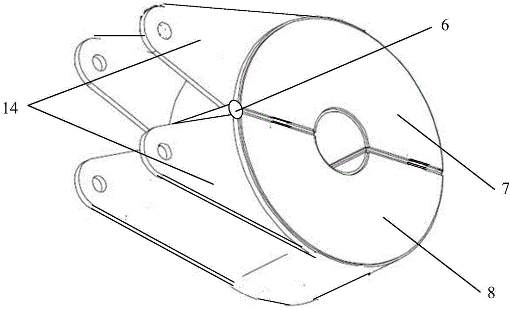
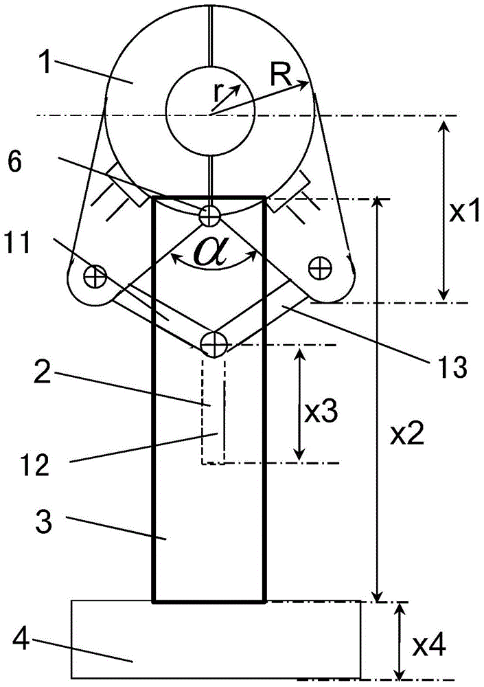
[0032]In this embodiment, the power cabinet can provide 8Hz, 1000A current, which can make the magnetic field rotate clockwise. The winding in the body 1 of the electromagnetic swirl device adopts cogging type concentrated winding. The height h of the body 1 of the electromagnetic swirl device is 80mm, the inner diameter r is 25mm, the outer diameter R is 80mm, and the opening and closing angle α is 10°. The distance x1 from the center of the electromagnetic swirl device body 1 to the lowermost end of the ear plate 14 is 100mm. The opening and closing control mechanism 2 adopts a pneumatic method, and the length x3 of the control end of the opening and closing control mechanism 2 is 200mm. The support rod 15 is a telescopic structure, which is driven by pneumatic means, and its length x2 after positioning is 600mm. The fixed steel plate 4 of the tundish beam is fixed on the tundish beam 5 by welding. The support rod 15 is fixedly connected with the fixed steel plate 4 of the...
Embodiment 2
[0034] In this embodiment, the power cabinet can provide a current of 100 Hz and 500 A, which can cause the magnetic field to rotate counterclockwise. The winding in the electromagnetic swirl device body 1 adopts toroidal (Clemme) windings. The height h of the electromagnetic swirl device body 1 is 300mm, the inner diameter r is 100mm, the outer diameter R is 300mm, and the opening and closing angle α is 90°. The distance x1 from the center of the electromagnetic swirl device body 1 to the lowermost end of the ear plate 14 is 600 mm. The opening and closing control mechanism 2 adopts a mechanical method, and the length x3 of the control end of the opening and closing control mechanism 2 is 300 mm. The support rod 15 is a telescopic structure, which is driven by mechanical means, and its length x2 after positioning is 1200mm. The fixed steel plate 4 of the tundish beam is fixed on the tundish beam 5 by means of bolt connection. The support rod 15 is fixedly connected with the...
Embodiment 3
[0036] In this embodiment, the power cabinet can provide 800Hz, 200A current, which can make the magnetic field rotate clockwise. The winding in the body 1 of the electromagnetic swirl device adopts a cogged type centralized winding. The height h of the electromagnetic swirling device body 1 is 500 mm, the inner diameter r is 150 mm, the outer diameter R is 500 mm, and the opening and closing angle α is 180°. The distance x1 from the center of the electromagnetic swirl device body 1 to the lowermost end of the ear plate 14 is 1000mm. The opening and closing control mechanism 2 adopts a pneumatic method, and the length x3 of the control end of the opening and closing control mechanism 2 is 500mm. The support rod 15 is of fixed length, and its length x2 is 2000mm. The fixed steel plate 4 of the tundish beam is fixed on the tundish beam 5 by welding. The support rod 15 is fixedly connected with the fixed steel plate 4 of the tundish beam by means of bolt connection.
PUM
| Property | Measurement | Unit |
|---|---|---|
| height | aaaaa | aaaaa |
| height | aaaaa | aaaaa |
Abstract
Description
Claims
Application Information
 - R&D
- Intellectual Property
- Life Sciences
- Materials
- Tech Scout
- Unparalleled Data Quality
- Higher Quality Content
- 60% Fewer Hallucinations
Browse by: Latest US Patents, China's latest patents, Technical Efficacy Thesaurus, Application Domain, Technology Topic, Popular Technical Reports.
© 2025 PatSnap. All rights reserved.Legal|Privacy policy|Modern Slavery Act Transparency Statement|Sitemap|About US| Contact US: help@patsnap.com


