Phase-controlled switch peak zero-cross-switching inrush current control circuit and control method

A control circuit and zero-crossing switching technology, which is applied to AC network circuits, emergency protection circuit devices for limiting overcurrent/overvoltage, circuit devices, etc., can solve problems such as large inrush current, large energy consumption, and high price

Active Publication Date: 2015-04-29
江苏南自通华智慧能源股份有限公司
View PDF8 Cites 8 Cited by
  • Summary
  • Abstract
  • Description
  • Claims
  • Application Information

AI Technical Summary

Problems solved by technology

[0007] The purpose of the present invention is to: propose a phase-controlled switch peak value zero-crossing switching inrush current control circuit, provide a corresponding control method at the same time, solve the technical problem of large inrush current on the traditional pre-charging circuit, and overcome the thyristor switching capacitor bank (TSC) ) Disadvantages of high price and high energy consumption

Method used


Image

  • Phase-controlled switch peak zero-cross-switching inrush current control circuit and control method
  • Phase-controlled switch peak zero-cross-switching inrush current control circuit and control method
  • Phase-controlled switch peak zero-cross-switching inrush current control circuit and control method

Examples


Embodiment 1

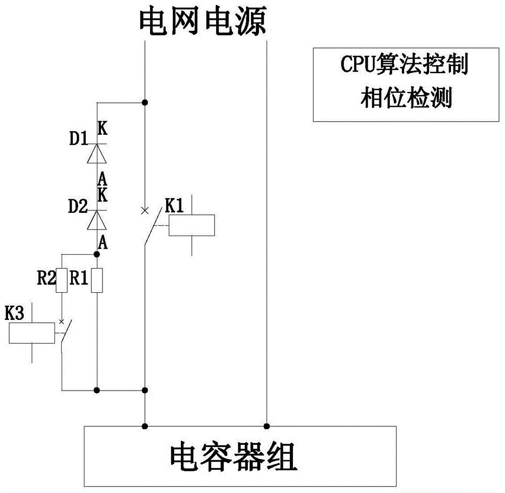
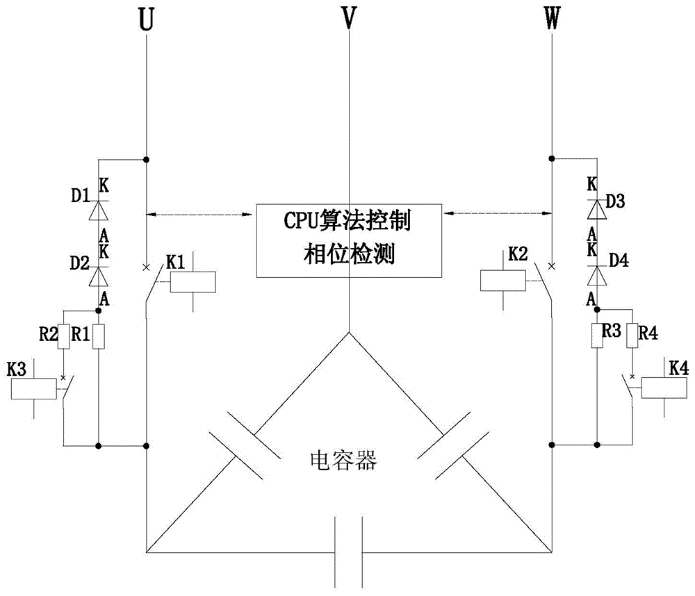
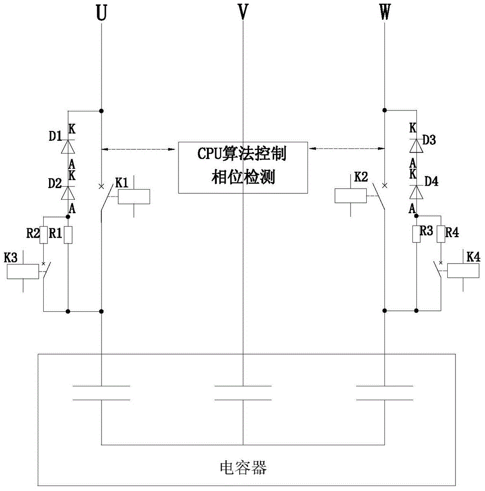
[0037] This embodiment is a phase-controlled switch peak zero-crossing switching inrush current control circuit applied in a 2-control 3 circuit of switching delta-connected capacitor banks, such as figure 2 As shown, it includes a control circuit including an intelligent control device CPU and two magnetic latching relay switches K1 and K2 that respectively control the two-phase on-off of the delta-connected capacitor bank and the three-phase grid power supply. Next to each magnetic latching relay switch K1 and K2 The main series circuit composed of two high-voltage diodes D1, D2, D3, D4 and corresponding high-resistance high-voltage current-limiting resistors R1, R3 are connected in parallel respectively. A secondary series circuit composed of an auxiliary relay switch K3 connected in parallel next to the high-voltage current-limiting resistor R1 and a low-resistance high-voltage current-limiting resistor R2 in series. A secondary series circuit composed of an auxiliary rel...

Embodiment 2

[0057] This embodiment is a phase-controlled switch peak value zero-crossing switching inrush current control circuit applied in a 2-control 3 circuit of switching star-connected capacitor banks, such as figure 2 As shown, its composition and control steps are the same as those in Embodiment 1, and will not be repeated here.


PUM


Abstract

The invention relates to a phase-controlled switch peak zero-cross-switching inrush current control circuit and a control method thereof, and belongs to the technical field of reactive compensation and harmonic filter of electric power systems. The control circuit comprises a control circuit which is provided with an intelligent control device and a magnetic latching relay switch which is used for controlling the connection and disconnection between a capacitor group and a network source, wherein a primary series circuit formed by a high-voltage diode and a high-resistance high-voltage current limiting resistor via series connection is connected beside the magnetic latching relay switch in parallel; a secondary series circuit formed by an auxiliary relay switch and a low-resistance high-voltage current limiting resistor via series connection is connected beside the high-voltage current limiting resistor in parallel; a zero-cross signal input end of the intelligent control device of the control circuit is connected with two ends of a contact of the magnetic latching relay switch; a detection end of a reference phase detection circuit is connected with the network source; a control output end is connected with controlled ends of a primary relay switch and a secondary relay switch. The phase-controlled switch peak zero-cross-switching inrush current control circuit and the control method can be used for solving the problem that the inrush current on the traditional pre-charging circuit is large and the capacitor group is easy to damage, and have the advantages of being energy-saving, environment-friendly, free of energy consumption and suitable for the switching control of multi-phase switched capacitor groups with various connection manners and different voltage classes.

Description

technical field [0001] The invention relates to an inrush current control circuit, in particular to a phase-controlled switch peak value zero-crossing switching inrush current control circuit, and at the same time relates to its control method, which is used in power grid power quality control projects and can realize fast and non-impact current for capacitor banks The input and cut off when the current crosses zero belong to the technical field of reactive power compensation and harmonic filter of electric power system. Background technique [0002] The power grid usually needs reactive power compensation to achieve the purpose of stabilizing the grid voltage, improving the power factor, and reducing line loss. Switching capacitor bank is the main method to realize reactive power compensation at present. However, the technical status of switched capacitor banks is not optimistic. [0003] In the field of reactive power compensation, about 80% use mechanical contact switch...

Claims


Application Information

Patent Timeline
Patent Type & Authority Applications(China)
IPC IPC(8): H02J3/18H02H9/02
CPCY02E40/30H02J3/1864H02J3/01
Inventor 徐魁陈晓庆徐清扬常新平
Owner 江苏南自通华智慧能源股份有限公司
Why Eureka
Try Eureka