A two-petal submerged nozzle electromagnetic swirling device and its supporting device

A technology of swirl device and support device, which is applied to casting melt containers, manufacturing tools, metal processing equipment, etc., can solve the problems of inconvenient on-site continuous casting operation, interruption of swirl effect, low magnetic field efficiency, etc., to ensure smooth operation. , The effect of controlling the flow of molten steel and high utilization of the magnetic field

Active Publication Date: 2017-10-20
NORTHEASTERN UNIV LIAONING
View PDF8 Cites 0 Cited by
  • Summary
  • Abstract
  • Description
  • Claims
  • Application Information

AI Technical Summary

Problems solved by technology

The commonly used electromagnetic swirl device with 360-degree overall ring structure will have a great impact on the existing continuous casting process; the magnetic field efficiency of the electromagnetic swirl device with 180-degree semi-circular structure is very low; The electromagnetic swirl device with body ring structure needs to fully consider frequent operations such as adding mold slag on site. If you always open and add mold slag, first, it will easily affect the equipment; second, it will cause interruption to the swirl effect; It also brings a lot of inconvenience to the operation of on-site continuous casting

Method used


Image

  • A two-petal submerged nozzle electromagnetic swirling device and its supporting device
  • A two-petal submerged nozzle electromagnetic swirling device and its supporting device
  • A two-petal submerged nozzle electromagnetic swirling device and its supporting device

Examples


Embodiment 1

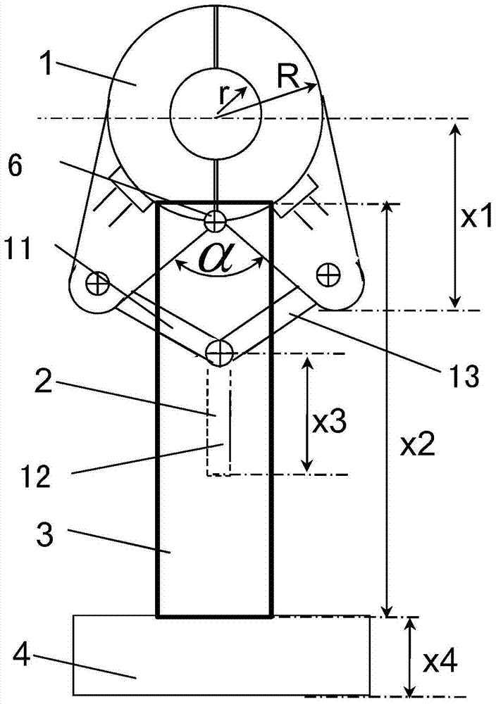
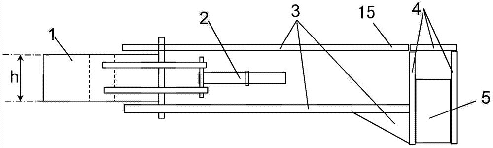
[0032]In this embodiment, the power cabinet can provide 8Hz, 1000A current, which can make the magnetic field rotate clockwise. The winding in the body 1 of the electromagnetic swirl device adopts the cogging type centralized winding. The height h of the body 1 of the electromagnetic swirl device is 80mm, the inner diameter r is 25mm, the outer diameter R is 80mm, and the opening and closing angle α is 10°. The distance x1 from the center of the electromagnetic swirl device body 1 to the lowermost end of the ear plate 14 is 100 mm. The opening and closing control mechanism 2 adopts a pneumatic method, and the length x3 of the control end of the opening and closing control mechanism 2 is 200mm. The support rod 15 is a telescopic structure, which is driven by pneumatic means, and its length x2 after positioning is 600mm. The fixed steel plate 4 of the tundish beam is fixed on the tundish beam 5 by welding. The support rod 15 is fixedly connected with the fixed steel plate 4 of...

Embodiment 2

[0034] In this embodiment, the power cabinet can provide a current of 100 Hz and 500 A, which can cause the magnetic field to rotate counterclockwise. The winding in the electromagnetic swirl device body 1 adopts toroidal (Clemme) winding. The height h of the electromagnetic swirl device body 1 is 300mm, the inner diameter r is 100mm, the outer diameter R is 300mm, and the opening and closing angle α is 90°. The distance x1 from the center of the electromagnetic swirl device body 1 to the lowermost end of the ear plate 14 is 600 mm. The opening and closing control mechanism 2 adopts a mechanical method, and the length x3 of the control end of the opening and closing control mechanism 2 is 300 mm. The support rod 15 is a telescopic structure, which is driven by mechanical means, and its length x2 after positioning is 1200mm. The fixed steel plate 4 of the tundish beam is fixed on the tundish beam 5 by means of bolt connection. The support rod 15 is fixedly connected with the ...

Embodiment 3

[0036] In this embodiment, the power cabinet can provide 800Hz, 200A current, which can make the magnetic field rotate clockwise. The winding in the body 1 of the electromagnetic swirl device adopts a cogged type centralized winding. The height h of the electromagnetic swirling device body 1 is 500 mm, the inner diameter r is 150 mm, the outer diameter R is 500 mm, and the opening and closing angle α is 180°. The distance x1 from the center of the electromagnetic swirl device body 1 to the lowermost end of the ear plate 14 is 1000 mm. The opening and closing control mechanism 2 adopts a pneumatic method, and the length x3 of the control end of the opening and closing control mechanism 2 is 500mm. The support rod 15 is of fixed length, and its length x2 is 2000mm. The fixed steel plate 4 of the tundish beam is fixed on the tundish beam 5 by welding. The support rod 15 is fixedly connected with the fixed steel plate 4 of the tundish beam by means of bolt connection.


PUM

PropertyMeasurementUnit
heightaaaaaaaaaa
heightaaaaaaaaaa

Abstract

A two-part type immersion type water opening electromagnetic cyclone device and a supporting device thereof belong to the technical field of continuous casting. The two-part type immersion type water opening electromagnetic cyclone device comprises an electromagnetic cyclone device body and an opening-closing control mechanism. The electromagnetic cyclone device body is internally provided with a winding. The electromagnetic cyclone device body is composed of a left half housing and a right half housing. The left half housing and the right half housing have two symmetrical semi-annular structures. The left half housing and the right half housing are respectively provided with a water inlet, a water outlet and a terminal. One end of the left half housing is connected with one end of the right half housing through a hinge connection, and the opposite side walls at the other end of the left half housing and the other end of the right half housing are respectively provided with a left half through trough and a right half through trough. After the left half housing and the right half housing are closed, the electromagnetic cyclone device body is annular; and the left half through trough and the right half through trough form a through hole, namely a protective slag adding opening. The non-hinged parts of the left half housing and the right half housing are respectively connected with the opening-closing control mechanism. The supporting device is composed of supporting rods. One end of the supporting rod is fixed on the hinge connection, and the other end is fixedly connected with an intermediate packaging crossbeam.

Description

technical field [0001] The invention belongs to the technical field of continuous casting, and in particular relates to a two-petal submerged nozzle electromagnetic swirling device and a supporting device thereof. Background technique [0002] With the development of continuous casting technology, high-quality billet has become the goal pursued by steel enterprises today. It is necessary to continuously develop new technologies for slab continuous casting that can stabilize the flow of molten steel in the mold and improve the quality of the slab. The flow state of molten steel in the mold directly affects the quality of the slab and the content and distribution of non-metallic inclusions. At present, the methods to improve the flow state of molten steel in the mold are mainly mold electromagnetic stirring, electromagnetic braking and other technologies. However, since the mold is made of copper plates that pass through water, the magnetic field is shielded by the copper pla...

Claims


Application Information

Patent Timeline
Patent Type & Authority Patents(China)
IPC IPC(8): B22D11/115B22D41/62
Inventor 王强赫冀成李德伟苏志坚丸川雄净
Owner NORTHEASTERN UNIV LIAONING
Why Eureka
Try Eureka