Compliant joint taking irregular plate spring with variable cross section as skeleton

A leaf spring and skeleton technology, applied in the field of leaf spring skeleton compliant joints, can solve problems such as the need to improve the dynamic response, the need to improve the dynamic response, and the uneven force of the leaf spring, so as to facilitate the analysis and calculation, improve the dynamic response, Avoid contact interference effects

Inactive Publication Date: 2015-06-10
JIANGNAN UNIV
View PDF6 Cites 0 Cited by
  • Summary
  • Abstract
  • Description
  • Claims
  • Application Information

AI Technical Summary

Problems solved by technology

Disadvantages: (1) Joint action space is small, and its bending angle is greatly restricted
(2) The force of the leaf spring is uneven. Using a general equal-section leaf spring will not only increase the deformation resistance and waste energy, but also increase the weight of the joint and waste materials.
(3) poor flexibility
The superiority of flexibility is reflected in reducing assembly time, simplifying the manufacturing process, improving precision, increasing reliability, reducing maintenance, and reducing quality. This patent has many parts and lacks necessary positioning measures. The bellows are connected by clamps, which is reliable Low reliability and troublesome replacement, which is not conducive to maintenance
(4) Dynamic response needs to be improved
Generally, the plate spring with equal cross-section has a large resistance when it starts to bend from a straight state, and requires a large pressure to start to move. Moreover, the overall mass of the joint is large and the inertia is large, so the dynamic response needs to be improved.

Method used


Image

  • Compliant joint taking irregular plate spring with variable cross section as skeleton
  • Compliant joint taking irregular plate spring with variable cross section as skeleton
  • Compliant joint taking irregular plate spring with variable cross section as skeleton

Examples


Embodiment Construction

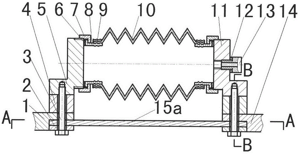
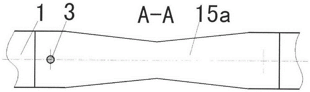
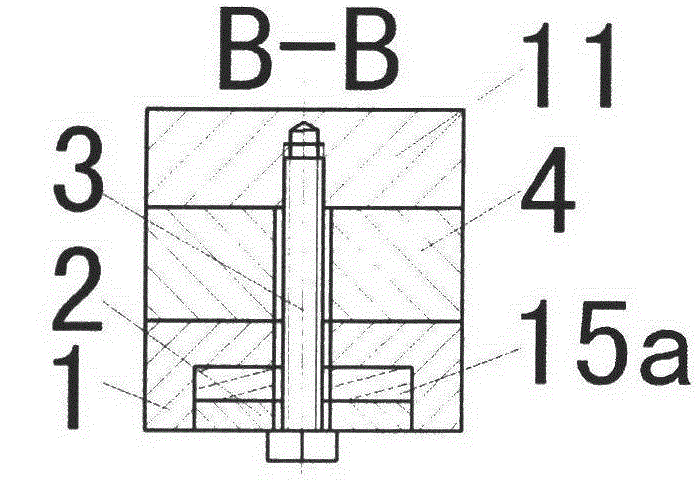
[0037] Below the present invention is combined with attached Figure 14 The first implementation of the scheme is further described:

[0038]In Scheme 1, the two ends of the elastic bellows 10 are fixed on the pipe joint 8 through the pressure piece 9, and the pipe joints 8 at both ends of the bellows are respectively connected with the headstock 5 and the tailstock 11, and are locked by the lock nut 7, with a Gasket 6 is sealed to form a gas cavity. There is an air inlet on the tailstock 11, and the air inlet pipe joint 13 is fixed on the tailstock 11 through the sealing ring 12. The headstock 5 and the tailstock 11 are respectively fixed with the head section 1 and the tail section 14 through the adjustment cushion block 4 . There are positioning pins on the upper and lower surfaces of the adjustment cushion block 4 to ensure the mutual positioning between the headstock 5 and the head section 1 as well as the tailstock 11 and the tail section 14. The two ends of the trape...


PUM


Abstract

The invention relates to a compliant joint taking an irregular plate spring with a variable cross section as a skeleton, and belongs to the technical field of rotor and mechanical arm application. The joint adopts the irregular plate spring with the variable cross section as the skeleton, is bent after being driven by fluid and can be used as various types of joints of a robot. When an elastic corrugated pipe is aerated, the elastic corrugated pipe extends and bends towards one side of the plate spring by being restrained by the plate spring; when gas in the elastic corrugated pipe is released, the joint is returned to the extending state under the action of the plate spring. Pressure in the elastic corrugated pipe is controlled to cause the joint to be bent at a certain angle. The elastic corrugated pipe has good flexibility, and the plate spring has good elasticity, therefore, the joint has good flexibility. Because the cross section and the shape of the plate spring are improved, the bending space can be enlarged, the strength requirement is complied, the flexibility is enlarged, and the plate spring material is saved. The joint has the advantages of being flexible in bending action, small in energy consumption, good in flexible self-adapting action and convenient to control.

Description

Technical field: [0001] The invention relates to a flexible joint of a plate spring skeleton with variable cross-section and special shape. The curved joint has good compliance and controllability, and can be used as various joints of robots, especially suitable for flexible joints composed of multiple curved joints. A mechanical finger, as an actuator of automation equipment, belongs to the technical field of robot and manipulator applications. Background technique: [0002] Before the present invention, the bending joints of robots were mostly driven by motors, which had good static stiffness and high control precision, but required complex deceleration devices, which were relatively large in size and not flexible enough; some were driven by pneumatic cylinders or hydraulic cylinders, which required complex fluids loop and the position control accuracy is not high. The current robot joints mostly use rigid skeletons, which require high precision in position and force, but...

Claims


Application Information

Patent Timeline
Patent Type & Authority Patents(China)
IPC IPC(8): B25J17/00
Inventor 章军刘光元刘传江吕兵
Owner JIANGNAN UNIV
Why Eureka
Try Eureka