Sheath metal belt unwinding device applied to production of optical cable

A technology for optical cables and metal strips, applied in the field of sheath metal strip unwinding devices, which can solve the problems of frequent movement of moving parts, unstable tension control, troublesome tension control, etc., and achieve compact structure, low operating cost, and easy tension control Effect

Active Publication Date: 2012-06-13
西安北方光通信有限责任公司
View PDF5 Cites 4 Cited by
  • Summary
  • Abstract
  • Description
  • Claims
  • Application Information

AI Technical Summary

Problems solved by technology

[0004] At present, the metal belts in the industry are paid off by hand, and the tension of the released line is adjusted by a tension control device. The operation of this kind of line is complicated, and the tension control is also very troublesome.
Among them, the tension control device is mostly controlled by a servo motor plus a screw nut, a wedge-shaped slider structure, or an electric control plus a weight structure, or an electric control plus a cylinder structure. The above-mentioned control devices move frequently relative to the moving parts and wear Large, high failure rate, large maintenance workload, and vulnerable to the influence of motor working current, making the tension control unstable

Method used


Image

  • Sheath metal belt unwinding device applied to production of optical cable
  • Sheath metal belt unwinding device applied to production of optical cable
  • Sheath metal belt unwinding device applied to production of optical cable

Examples


Embodiment Construction

[0018] Below in conjunction with accompanying drawing and specific embodiment the utility model is described in detail:

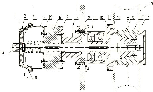
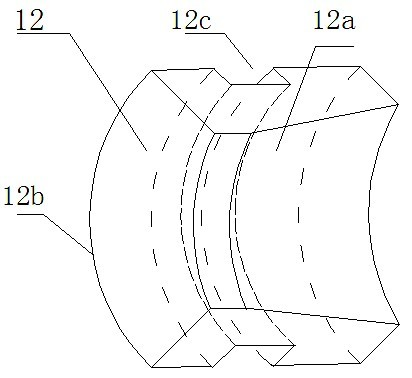
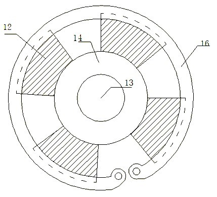
[0019] control figure 1 The sheath metal tape unwinding device in the optical cable production of this embodiment is mainly composed of an air cushion cover 1, an air cushion 2, a baffle plate 3, a spring 4, an air cushion cover flange 5, a magnetic powder brake 6, a transmission shaft bearing seat 7, and a lifting plate 8. Outer shell bearing seat 9, outer shell connecting flange 10, outer shell 11, expansion sleeve inclined block 12, transmission shaft 13, inner sleeve 14, magnetic powder brake gasket 15, retaining spring 16, material blocking plate 17 and air cushion cover connector 18 constitute. The air cushion 2 is close to the inner surface of the air cushion cover 1, the circumferential edges of the air cushion cover 1 and the air cushion 2 are sealed and connected, the baffle 3 is close to the air cushion, and the center of the baffle 3 is provi...


PUM


Abstract

The invention relates to a sheath metal belt unwinding device applied to production of an optical cable. The sheath metal belt unwinding device comprises an air cushion cover, an air cushion, a spring, a baffle plate, an air cushion cover flange, a magnetic powder brake, a transmission shaft bearing pedestal, a lifting plate, an outer sleeve bearing pedestal, an outer sleeve connection flange, anouter sleeve, a plurality of expansion sleeve inclined blocks, a clamping spring and an inner sleeve, wherein one end of a transmission shaft is connected with the baffle plate in a rotatable manner;the air cushion cover is arranged at the outer end of the baffle plate; one side of the magnetic powder brake, which is opposite to the baffle plate, is connected with the air cushion cover flange, and the other side of the magnetic powder brake is provided with the lifting plate; opposite sides of the magnetic powder brake and the lifting plate are connected with each other through the transmission shaft bearing pedestal; the transmission shaft is supported on the bearing pedestal through a corresponding bearing; the outer sleeve bearing pedestal is connected to the other side face of the lifting plate; the outer sleeve connection flange is sleeved on the transmission in a hollow manner; the outer sleeve connection flange is connected with the outer sleeve; the inner sleeve is connected to the other end of the transmission shaft; and a plurality of holes in the circumferential direction of the outer sleeve are correspondingly inserted with the expansion sleeve inclined blocks. The sheath metal belt unwinding device has the advantages of small impact, low abrasion, simple operation, safety, reliability and compact structure.

Description

[0001] technical field [0002] The invention relates to the technical field of optical and cable manufacturing, in particular to a sheath metal tape unwinding device in the production of optical cables in the production of optical cables. Background technique [0003] In order to prevent small animals or insects from biting the cable, a metal layer (metal tape) should be wrapped on the outer layer of the light and cable. The metal strip is wound on the corresponding disc as the raw material for the production of light and cable. When producing light and cable, the metal strip needs to be released from the disc. [0004] At present, the metal belts in the industry are paid off by hand, and the tension of the released wire is adjusted by a tension control device. The operation of this kind of wire release is complicated, and the tension control is also very troublesome. Among them, the tension control device is mostly controlled by a servo motor plus a screw nut, a wedge-sh...

Claims


Application Information

Patent Timeline
Patent Type & Authority Applications(China)
IPC IPC(8): B65H59/38B65H49/18
Inventor 王振云徐竞奕顾小成
Owner 西安北方光通信有限责任公司
Why Eureka
Try Eureka