
Prefabricated L-shaped retaining structure

A support structure and L-shaped technology, applied in the field of prefabricated L-shaped support structures, can solve the problems of insufficient road shoulder width to meet the requirements, large traffic interference on existing lines, and limited height of the ballast wall, so as to shorten the construction period, Conducive to the effect of stability and simple structure

Inactive Publication Date: 2012-06-13
CHINA RAILWAY FIFTH SURVEY & DESIGN INST GRP
View PDF10 Cites 6 Cited by
  • Summary
  • Abstract
  • Description
  • Claims
  • Application Information

AI Technical Summary

Problems solved by technology

[0005] The amount of earthwork for filling soil on the side slope of the subgrade is large, which will easily lead to new land acquisition. The protective masonry of the old subgrade slope needs to be removed, and the masonry protection of the side slope after the side filling needs to be resumed, because it will greatly interfere with the traffic on the existing line. ; When the retaining wall is installed on the road shoulder, the setting height of the retaining wall is limited, which cannot meet the requirements for serious subgrade subsidence and insufficient width of the road shoulder. The excavation of the foundation pit of the retaining wall and the long-term construction interfere greatly with the traffic on the existing line
Therefore, there are many problems in the environment, safety, work efficiency, economy and working hours in the main technologies of raising the roadbed surface and widening the roadbed surface and road shoulder width in the prior art

Method used


Image

  • Prefabricated L-shaped retaining structure
  • Prefabricated L-shaped retaining structure
  • Prefabricated L-shaped retaining structure

Examples


Embodiment Construction

[0020] The preferred embodiment of the L-shaped support structure of the present invention is as follows: Figure 1 to Figure 8 Shown:

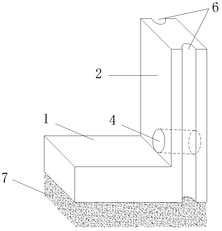
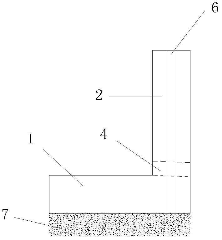
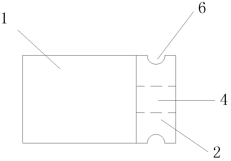
[0021] It includes a base plate 1, one end of the base plate 1 is connected with a straight wall 2, the height of the straight wall 2 is greater than or equal to the length of the base plate 1, and a drain hole 4 is provided at the bottom of the straight wall 1. The lower edge of the drain hole 4 is flush with the upper plane of the base plate 1, the upper surface of the base plate 1 and the inner surface of the straight wall 2 are respectively provided with hoisting rings 5, and the two sides of the straight wall 2 are respectively provided with An assembling hole 6 is arranged, and the assembling hole 6 is a semi-cylindrical hole penetrating up and down.

[0022] The bottom plate 1 and the straight wall 2 are integral prefabricated structures of reinforced concrete.

[0023] The bottom plate 1 is perpendicular to the straight wall 2 .

...


PUM


Abstract

The invention discloses a prefabricated L-shaped retaining structure, which comprises a bottom plate, wherein a straight wall is connected to one end of the bottom plate; the height of the straight wall is more than or equal to the length of the bottom plate; the middle position of the bottom of the straight wall is provided with a drainage hole; the lower edge of the drainage hole is flush with the upper plane of the bottom plate; the upper surface of the bottom plate and the inner surface of the straight wall are respectively provided with a hanging ring; two sides of the straight wall are respectively provided with a splicing hole; and each splicing hole is a semi-cylindrical hole which is penetrated up and down. The prefabricated L-shaped retaining structure disclosed by the invention has the advantages of reasonable design, simple structure, safety and reliability, convenience for assembly and disassembly, strong adaptability and capability of being safely, rapidly, repeatedly, efficiently and economically applied to regulation works, such as existing railway subgrade settlement, incapability of meeting design requirements by subgrade surface width, or insufficient with of road shoulder and the like.

Description

technical field [0001] The invention relates to an existing railway subgrade reinforcement technology, in particular to a prefabricated L-shaped retaining structure applied to the existing railway subgrade reinforcement. Background technique [0002] The railway subgrade is a geotechnical structure that works under various complex actions. It not only bears the full weight of the railway track, but also withstands the repeated action of train loads, and is often subjected to natural stresses such as water flow, wind and sand, rain and snow, severe cold, high temperature, and earthquakes. The impact of invasion and various adverse geological conditions and human factors. Subgrade subsidence, subgrade surface width not meeting the design requirements, or insufficient shoulder width are common diseases of existing railway subgrades. Repair these deformations and diseases, keep all parts of the road base and auxiliary equipment in good condition, improve its strength and stabil...

Claims


Application Information

Patent Timeline
Patent Type & Authority Applications(China)
IPC IPC(8): E01B2/00E02D29/02
Inventor 郭绍影冷长明
Owner CHINA RAILWAY FIFTH SURVEY & DESIGN INST GRP
Learn More