Multi-field coupling energy-saving tuned mass vibration reduction device

A vibration damping device and quality tuning technology, applied in building components, shockproof, etc., can solve the problems of hindering the movement of permanent magnets, low damping ratio, heat dissipation, etc., achieving clear and reliable principles, low cost, and strong operability Effect

Active Publication Date: 2012-06-13
中铁桥研科技有限公司 +2
View PDF4 Cites 10 Cited by
  • Summary
  • Abstract
  • Description
  • Claims
  • Application Information

AI Technical Summary

Problems solved by technology

The prior art closest to the present invention is the invention with the patent number CN201010022003.7, the publication number CN101761146A, the publication date is 2010.06.30, and the name is "Permanent Magnetic Eddy Current Tuning Mass Damper". The movement forms an induced current on the surface of the metal conductor, which in turn hinders the movement of the permanent magnet; but the invention has the following defects in practical application: 1. Since the linear bearing seat hangs upside down on the circular shaft, the mass block will be in contact with the circular shaft. Shaking in the plane perpendicular to the axis leads to insufficient stability of the device structure; 2. Only one side of the mass block is used to arrange the magnet, the vibration reduction effect is not ideal, and the damping ratio is not high; 3. By adjusting the distance between the permanent magnet and the metal conductor Adjusting the damping ratio has certain restrictions on damping adjustment. The induced current heats up and dissipates in the eddy current, resulting in the unused energy absorbed by the vibration reduction. There is a large amount of energy that is only consumed by the eddy current and not recycled.

Method used


Image

  • Multi-field coupling energy-saving tuned mass vibration reduction device
  • Multi-field coupling energy-saving tuned mass vibration reduction device

Examples


Embodiment Construction

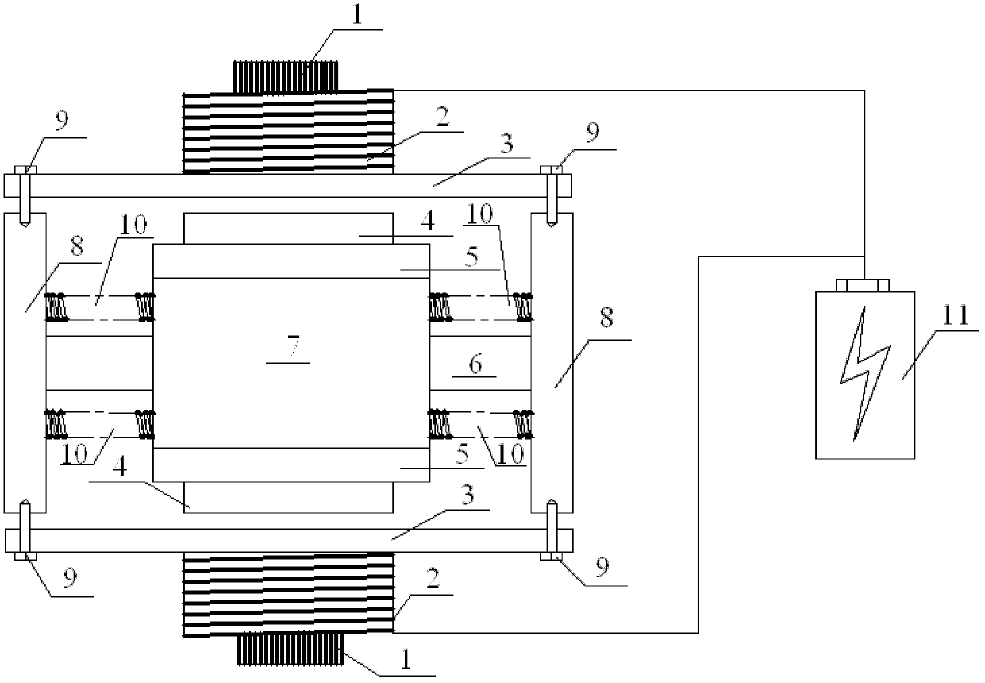
[0016] The present invention will be further described below in conjunction with the accompanying drawings and embodiments. This embodiment is a simulation test for the vibration suppression of a certain engineering structure. The natural frequency of the vibration reduction of the structure is w=15, and the optimal damping ratio is 4%-6%. According to the vibration reduction requirements of the engineering structure, the mass block is determined. The size of the iron block 7 is 100mm×100mm×100mm, the material is Q235 steel, and the weight is 16kg; the material of the end plate 8 is Q235 steel, the size is 150mm×150mm×10mm; there are four springs 10 between the end plate 8 and the iron block 7 The stiffness coefficient k=3619N / m; the size of the aluminum plate 3 is 150mm×400mm×20mm; the size of the rubber pad 5 is 10mm×100mm×100mm; the strength of the strong magnet 4 is 5000 gauss, and the size is 10mm×60mm×60mm; The two ends of the coil 2 generate a voltage of 5V, which can d...


PUM


Abstract

The invention provides a multi-field coupling energy-saving tuned mass vibration reduction device. By using power-electricity-magnetism-heat multi field coupling, aluminum sheets cut magnetic induction lines so as to change vibration mechanical energy into electric energy aiming at the vibration excitation of the external on an engineering structure, the aluminum sheets are fixed by using screws,the damping ratio can be adjusted by adjusting the distance between the aluminum sheets and a strong magnet, and a copper coil is fixed at the backs of the aluminum sheets to absorb energy which is generated by eddy current in the aluminum sheets, so current is generated in the copper coil; a nickel steel sheet is inserted into the copper coil to increase the magnetic flux density of the copper coil; the diameter and number of turns of the coil are adjusted, the number of the nickel steel sheet is increased, and the size of the nickel steel sheet is adjusted to ensure that current with different magnitudes is generated in the copper coil, so the damping ratio can be adjusted; and meanwhile, the current in the copper coil is stored in a storage battery in a charging way, so the power supply demand of structural illumination or sight can be met.

Description

technical field [0001] The invention relates to a vibration damping device for suppressing structural vibration, which is especially suitable for vibration control of construction engineering structures, belongs to the technical field of engineering structure vibration reduction, and specifically relates to a vibration damping device capable of suppressing engineering structure vibration and having converted electric energy for storage Vibration reduction device. Background technique [0002] With the continuous development of science and technology, the span of engineering structures is getting larger and higher, and the structure will generate relatively strong vibration under the action of external dynamic loads such as earthquakes or strong winds, which will seriously affect the stiffness of the structure and increase The fatigue and damage of the structure will eventually lead to the failure of the structure or even catastrophic accidents before the design life is reach...

Claims


Application Information

Patent Timeline
Patent Type & Authority Applications(China)
IPC IPC(8): E04B1/98
Inventor 王波王翔方华兵张奇志李东超荆国强柴小鹏郭翠翠尹红王鸣辉刘金平
Owner 中铁桥研科技有限公司
Why Eureka
Try Eureka