Novel optical calibration equipment of radio-frequency simulated target antenna array

A radio frequency simulation and antenna array technology, applied in the direction of optical devices, measuring devices, instruments, etc., can solve the problems of inability to communicate directly and effectively, and achieve the effect of easy fine adjustment, convenient adjustment, and consistent electromechanical characteristics

Inactive Publication Date: 2012-06-13
NANJING UNIV OF AERONAUTICS & ASTRONAUTICS
View PDF3 Cites 14 Cited by
  • Summary
  • Abstract
  • Description
  • Claims
  • Application Information

AI Technical Summary

Problems solved by technology

[0006] The purpose of the present invention is to provide a new type of radio frequency simulation target antenna array optics for the traditional optical calibration, where the distance measuring personnel and the installation and debugging personnel are respectively located on both sides of the spherical screen and cannot communicate directly and effectively. The calibration device uses the camera to collect the rangefinder screen display and the rangefinder laser point at the position of the antenna mouth into an image, and transmits it to the installation and debugging personnel after the spherical screen through the network, so that the installation and debugging personnel can intuitively obtain measurement data and image information, thereby make precise adjustments

Method used


Image

  • Novel optical calibration equipment of radio-frequency simulated target antenna array
  • Novel optical calibration equipment of radio-frequency simulated target antenna array
  • Novel optical calibration equipment of radio-frequency simulated target antenna array

Examples


Embodiment Construction

[0019] The present invention will be described in detail below in conjunction with the accompanying drawings and specific embodiments.

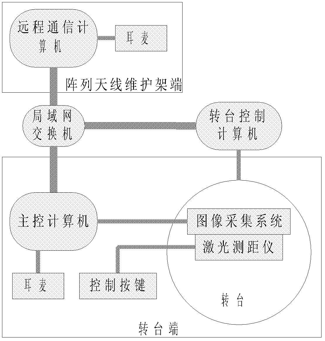
[0020] The structure of the new radio frequency simulation target antenna array optical calibration device is as follows: figure 1 shown.

[0021] The new radio frequency simulation target antenna array optical calibration device consists of a laser ranging system installed on a turntable, video image acquisition

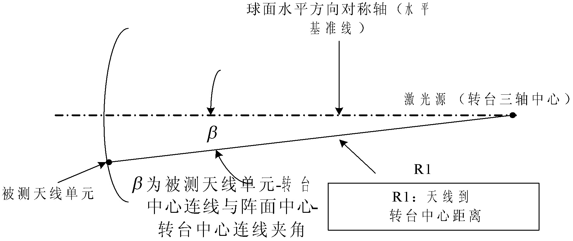
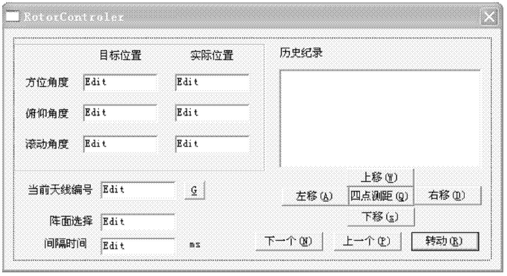
[0022] It consists of a system and a computer control and communication system. The laser ranging system is used to measure the distance from the antenna to the center of the turntable. The video image acquisition system is used to obtain the optical image of the antenna and convert it into an electronic image. The computer control and communication system is used to control the The steering and positioning of the turntable, receiving the electronic image generated by the video image acquisition system and displaying it on the scr...


PUM


Abstract

The invention discloses novel optical calibration equipment of a radio-frequency simulated target antenna array. The equipment is composed of a laser range-measurement system mounted on a rotary table, a video image acquisition system and a computer control and communication system, wherein the laser range-measurement system is used for measuring the distance between an antenna and the center of the rotary table; the video image acquisition system is used for obtaining an optical image of the antenna and converting the optical image into an electronic image; and the computer control and communication system is used for controlling the turning positioning of the rotary table, receiving the electronic image generated by the video image acquisition system and displaying the electronic image on a screen. Through adoption of the equipment provided by the invention, a mounting position and a spacing of a geometric center of each antenna surface meet design precision requirement, so that the difference in amplitude-phase characteristics among all paths of radiation signals of radiation interfaces of all antenna units is reduced and the fine adjustment of an electric characteristic becomes convenient so as to reach the consistency of electromechanical characteristics. Furthermore, through functions of voice communication and image transmission, workers can accurately obtain measured data and image information of the rotary table in time and the antenna can be conveniently and efficiently adjusted.

Description

[0001] technical field [0002] The invention relates to an optical calibration device applied to a target antenna array of a radio frequency simulation system, and belongs to the field of radar seeker radio frequency simulation. [0003] Background technique [0004] In order to ensure that the target positioning accuracy of the RF simulation system meets the accuracy requirements, it needs to be calibrated. Calibration is divided into two parts: mechanical calibration and electrical calibration. The mechanical calibration mainly calibrates the installation position of the array antenna; the electrical calibration receives the signal sent by the antenna array through the receiving device, and completes the calibration of the electrical performance of the RF feed system. The implementation of the calibration work is inseparable from the calibration device. The performance of the calibration device in the calibration system directly affects the calibration accuracy and dete...

Claims


Application Information

Patent Timeline
IPC IPC(8): G01B11/00G01B11/02
Inventor 周永刚朱根才臧春华张一帆
Owner NANJING UNIV OF AERONAUTICS & ASTRONAUTICS
Why Eureka
Try Eureka