
Laser illuminator capable of continuously regulating illumination angle in large scale and regulating method thereof

A technology of lighting angle and illuminator, which is applied in the parts of lighting devices, lighting devices, lighting and heating equipment, etc., can solve the problems of affecting the life of the laser, short lighting distance, and difficulty in giving full play to the advantages of the laser.

Inactive Publication Date: 2012-06-13
SHENZHEN GEDAD TECH
View PDF12 Cites 9 Cited by
  • Summary
  • Abstract
  • Description
  • Claims
  • Application Information

AI Technical Summary

Problems solved by technology

[0004] But the lighting device of above-mentioned prior art has the following problems: one, the viewfinder wide angle of camera has reached 60 degrees at present, and the maximum angle of existing laser illuminator on the market is much smaller than the wide angle required by camera, just produced Obvious "flashlight" effect; second, the laser energy utilization rate of the semiconductor laser is not high, it will generate a lot of heat, affect the life of the laser, and the lighting distance is short, it is difficult to take advantage of the long-distance lighting of the laser; third, it is difficult to take into account the small Angle illumination and semiconductor laser energy utilization rate make the illumination range unable to adapt to the required field of view angle; Fourth, the volume is too large, which affects the application range

Method used


Image

  • Laser illuminator capable of continuously regulating illumination angle in large scale and regulating method thereof
  • Laser illuminator capable of continuously regulating illumination angle in large scale and regulating method thereof
  • Laser illuminator capable of continuously regulating illumination angle in large scale and regulating method thereof

Examples


Embodiment Construction

[0023] Various preferred embodiments of the present invention will be described in more detail below in conjunction with the accompanying drawings.

[0024] At present, the laser illuminators on the market have the problems of difficulty in adjusting the size and angle and the low utilization rate of light energy, but the present invention can effectively solve the above problems, so that the field of view angle of the camera and the supplementary light angle of the illuminator are completely matched, And the supplementary light distance fully satisfies the photographing distance of cameras on the market, and at the same time, the supplementary light angle of the lighting device of the present invention is adjustable.

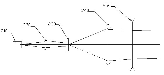
[0025] A preferred embodiment of the laser illuminator that can continuously adjust the illumination angle in a large range in the present invention, such as figure 2 According to the shown optical path principle, the laser illuminator of the present invention...


PUM


Abstract

The invention discloses a laser illuminator capable of continuously regulating an illumination angle in a large scale and a regulating method thereof. The laser illuminator comprises a laser for emitting lasers, and is sequentially provided with a short-focus lens and a homogenizing device; the laser, the short-focus lens and the homogenizing device are sequentially arranged on the same optical axis, the optical axis is further sequentially provided with a positive lens and a negative lens, and the positive lens can move along the optical axis forwards and backwards. The laser illuminator capable of continuously regulating the illumination angle in the large scale and the regulating method thereof, disclosed by the invention, utilizes a design scheme that the positive lens is arranged in the front of the negative lens, thus problems that a laser illuminator in the current market is hard to compatibly regulate the illumination angle and has lower utilization ratio of light energy are overcome, a vision angle of a camera and a light supplementing angle of an illuminator can be totally matched, and a light supplementing distance can totally meet a pickup distance of the camera in the market.

Description

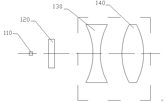
technical field [0001] The invention relates to a laser lighting device and method, in particular to a laser lighting supplementary light device and an adjustment method thereof which can continuously adjust the lighting angle in a large range. Background technique [0002] In the prior art, with the development of night camera technology, such as night monitoring, infrared light sensing technology is usually used, which requires infrared lighting; the technology of using infrared laser lighting (fill light) is becoming more and more common, and the requirements for lighting quality are getting higher and higher. come higher. [0003] However, because the light output angle of the semiconductor laser is fixed, the illumination distance will be limited. At present, the inverted Galilean telescope structure composed of positive and negative lenses is mostly used in the market to complete the function of adjustable illumination angle, such as figure 1 As shown, the laser ligh...

Claims


Application Information

Patent Timeline
Patent Type & Authority Applications(China)
IPC IPC(8): G03B15/05G02B27/09F21V14/06
Inventor 陆知纬
Owner SHENZHEN GEDAD TECH
Learn More