
Novel dovetail groove guide fixture

A dovetail-oriented and dovetail-slot technology, applied in semiconductor devices, sustainable manufacturing/processing, electrical components, etc., can solve the problems affecting the ingot loading efficiency, safety, slicing effect and service life, affecting the ingot loading efficiency and Safety and slicing effect, affecting the efficiency and safety of the ingot on the machine, to achieve the effect of improving efficiency and safety, slicing effect, improving operational safety, and improving the yield of slicing

Inactive Publication Date: 2012-06-13
JIANGSU MEIKE SILICON ENERGY
View PDF6 Cites 2 Cited by
  • Summary
  • Abstract
  • Description
  • Claims
  • Application Information

AI Technical Summary

Problems solved by technology

[0003] In the process of upper and lower crystal ingots, the dovetail groove tooling currently used in the industry has the following three problems: 1. The dovetail guide bar device, the inverted "T" shaped platform at the lower end and the connecting block in the middle are two independent parts. After use, the inverted "T"-shaped platform below will loosen, which affects the efficiency and safety of the ingot on the machine on the one hand, and affects the slicing quality of the ingot on the other hand
[0004] 2. When the fixed bracket and the inner wall of the machine, the fixed bracket and the dovetail guide device at the lower end are fixed with screws, there is no gasket installed. After long-term use, due to the vibration of the equipment and the impact of the crystal rod guide rail, the overall loosening
Affects the efficiency and safety of the ingot on the machine and the slicing effect
[0005] 3. The thickness of the fixed bracket is relatively thin. After being impacted by the guide rail of the ingot for a long time, if it is deformed, it will affect the efficiency, safety, slicing effect and service life of the ingot on the machine.

Method used


Image

  • Novel dovetail groove guide fixture
  • Novel dovetail groove guide fixture
  • Novel dovetail groove guide fixture

Examples


Embodiment Construction

[0019] The present invention is described in detail below in conjunction with accompanying drawing

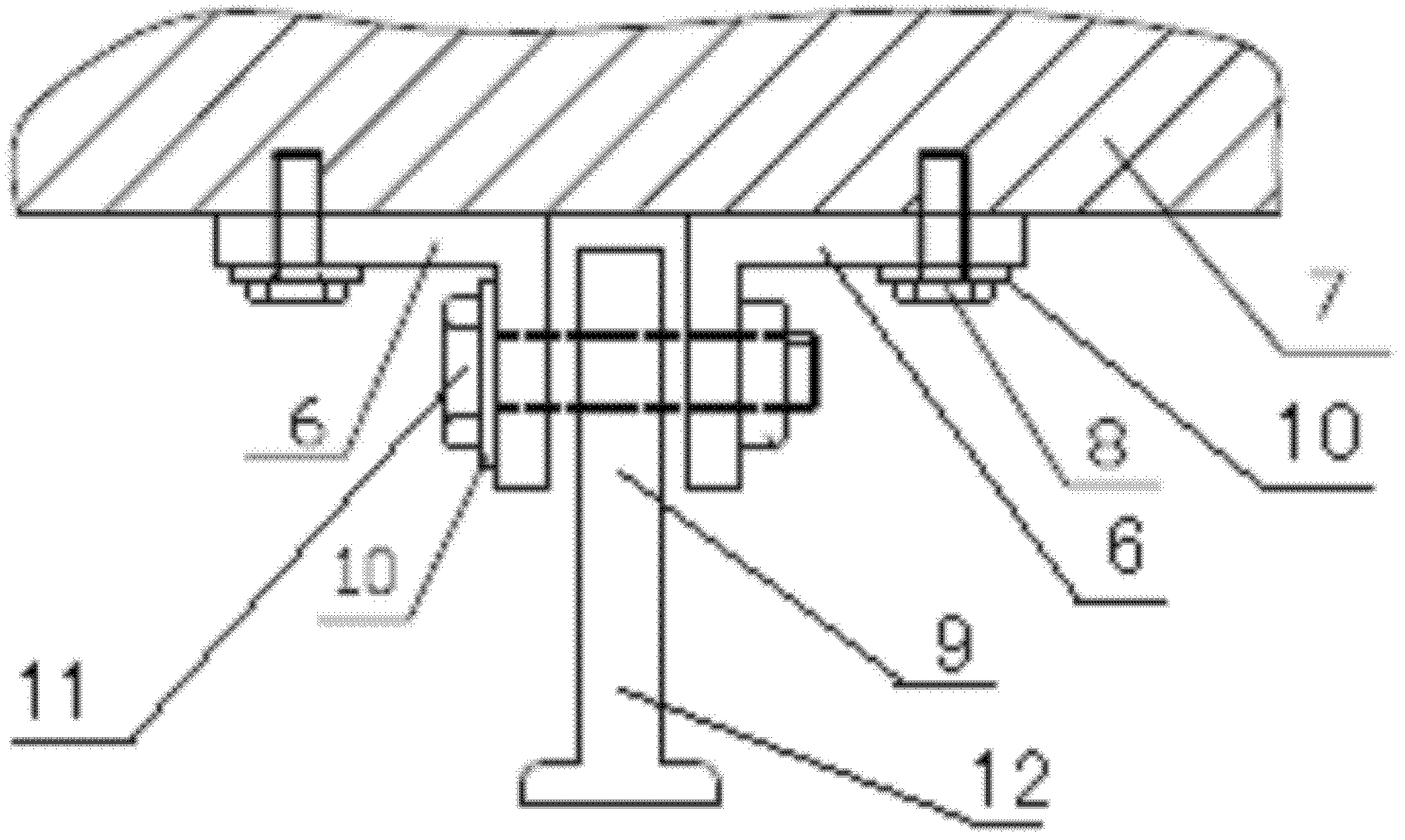
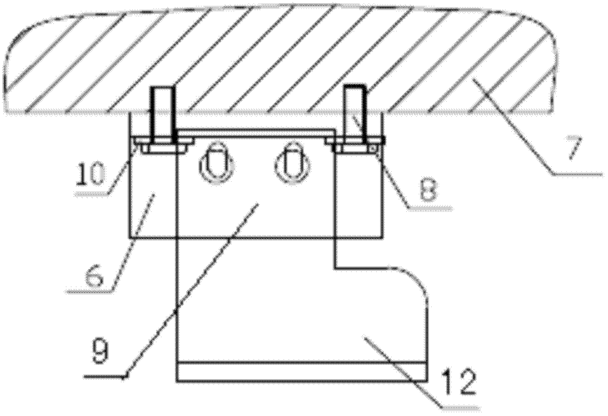
[0020] A new type of dovetail guide tooling, including: two fixed brackets 6 and a dovetail guide strip device, the fixed bracket 6 is in the shape of "L", and the two fixed brackets 6 are fixedly connected to the inner wall 7 of the equipment through the fixed bracket screws 8, respectively. The dovetail guide bar device comprises the inverted "T" shape guide platform 12 below the connecting plate 9 and the connecting plate 9, the connecting plate 9 is fixed in the middle of the two fixing brackets 6 by the connecting plate screw 11, and the inverted “T” below the connecting plate 9 and the connecting plate 9 "T" shape guide platform 12 is combined into a whole.

[0021] The thickness of the two fixing brackets 6 is 3mm-4mm, and the material is chrome.

[0022] Also includes gasket 10, gasket 10 is provided on the fixing bracket screw 8, gasket 10 is provided on the connectin...


PUM


Abstract

The invention discloses a novel dovetail groove guide fixture which comprises two fixing brackets and a dovetail groove guide strip device, wherein the fixing brackets are in an L shape; the two fixing brackets are fixedly connected with the inner wall of equipment through fixing bracket screws respectively; the dovetail groove guide strip device comprises a connecting plate and an inverted T-shaped guide platform below the connecting plate; the connecting plate is fixed between the two fixing brackets through connecting plate screws; and the connecting plate is integrated with the inverted T-shaped guide platform below the connecting plate. The effects of prolonging the service life, reducing the operating time and improving the operating safety and slicing yield can be achieved, the guide fixture has a simple structure, and crystal bar collision in the process of loading a crystal bar and crystal bar jitter in the process of unloading the crystal bar can be effectively controlled.

Description

technical field [0001] The invention relates to a tool used in the production and processing of silicon materials in the solar photovoltaic power generation industry, and more specifically relates to a new type of dovetail guide tooling, which belongs to the field of transition devices for crystal rods to enter the workpiece platform of a slicing machine from an upper and lower rod car. Background technique [0002] With the rapid development of the integrated circuit and photovoltaic industry, the processing technology and cost control of silicon materials are getting more and more attention. At present, the process of square cutting and slicing of each company is roughly the same. How can we achieve better results under the same process? Good efficiency requires attention to details. The slicing process is the most critical process in the entire industrial chain. The step of loading and unloading ingots is a key step in the slicing process and a key factor affecting the sli...

Claims


Application Information

Patent Timeline
Patent Type & Authority Applications(China)
IPC IPC(8): H01L31/18
CPCY02P70/50
Inventor 王友王禄宝徐勇袁志钟
Owner JIANGSU MEIKE SILICON ENERGY
Learn More