
Modeling method and system for correcting and predicting arc extinguishing angle

A modeling method and arc extinguishing angle technology, applied to output power conversion devices, electrical components, circuit devices, etc., can solve problems such as inability to measure the arc extinguishing angle, unfavorable system stability, and poor results

Inactive Publication Date: 2013-11-13
SHANDONG UNIV
View PDF2 Cites 2 Cited by
  • Summary
  • Abstract
  • Description
  • Claims
  • Application Information

AI Technical Summary

Problems solved by technology

[0003] 1. The subsynchronous resonance problem caused by DC transmission;
[0004] 2. The self-excitation problem of the generator connected to the converter station;
[0006] 4. The response of the DC system under different AC system strengths and different AC side faults;
[0007] 5. Transformer saturation and magnetic bias problems;
[0008] 6. The ferromagnetic resonance problem of the converter transformer;
[0009] 7. Harmonics and low-order resonance problems caused by DC transmission;
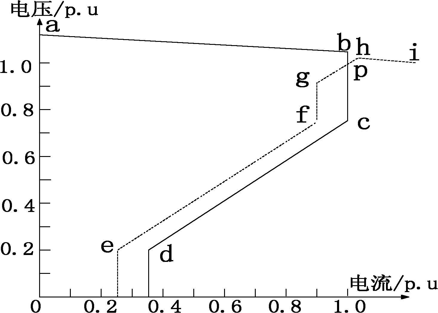
However, there are also some DC systems (such as Yindong ±660kV DC system) because the converter valve and the control system are not produced by the same unit, and there is a certain degree of mismatch, which makes it impossible to measure the arc-extinguishing angle, which makes it difficult to use fixed arc-extinguishing angle control , while the AC system on the inverter side is relatively stable, and the effect of constant voltage control is not good, so a new control method is needed, which is the predictive arc-extinguishing angle control method, but the control curve of the arc-extinguishing angle on the inverter side is not It must be a positive slope, which is not conducive to the stability of the system

Method used


Image

  • Modeling method and system for correcting and predicting arc extinguishing angle
  • Modeling method and system for correcting and predicting arc extinguishing angle
  • Modeling method and system for correcting and predicting arc extinguishing angle

Examples


Embodiment Construction

[0051] Below in conjunction with accompanying drawing and embodiment the present invention will be further described:

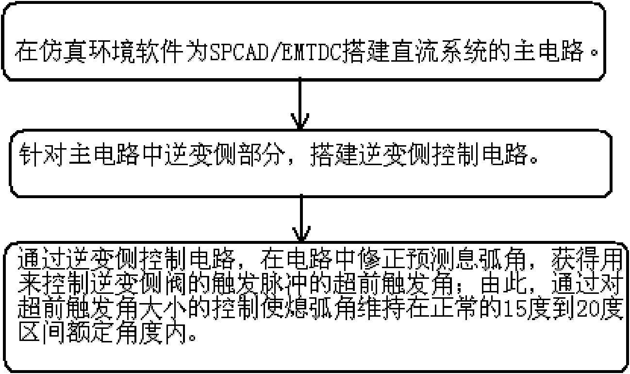
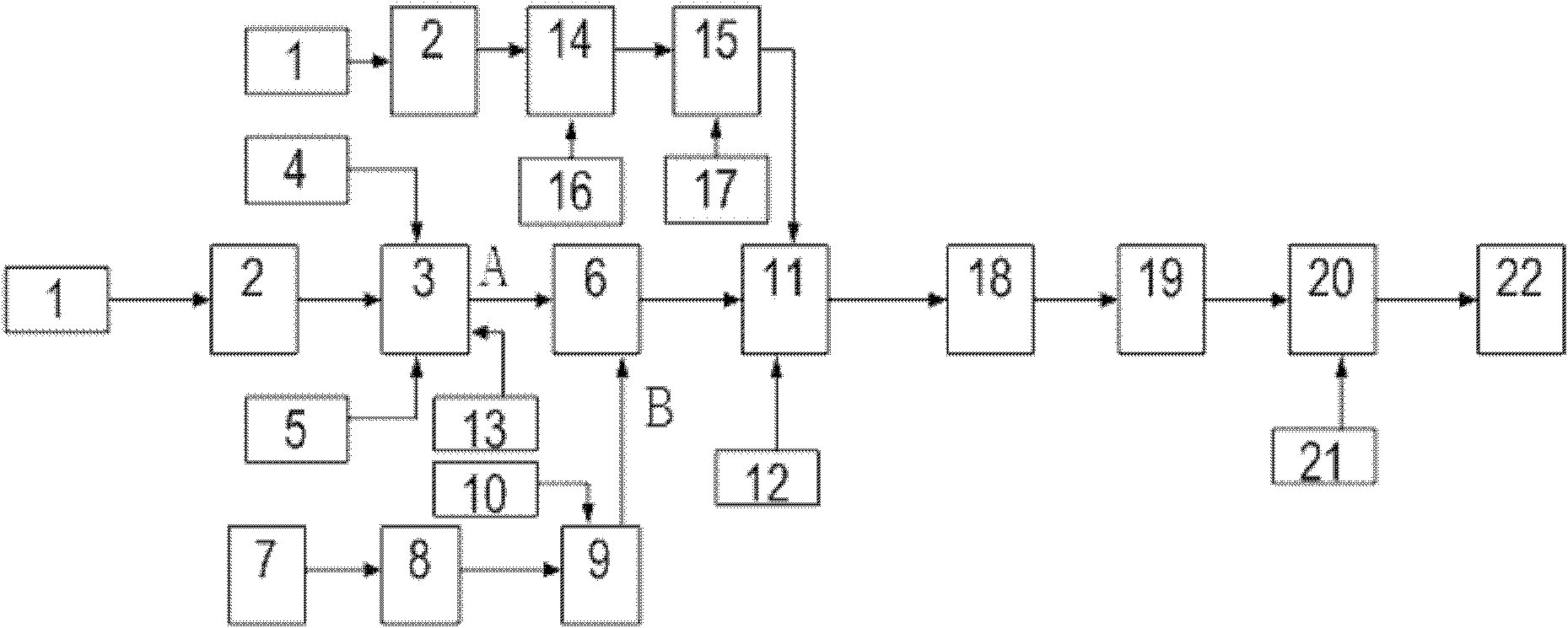
[0052] figure 1 , figure 2 Among them, a method and system for correcting and predicting the arc-extinguishing angle modeling are specifically implemented, and the specific steps it includes are as follows: 1) Build the main circuit of the DC system for PSCAD / EMTDC in the simulation environment software; the main circuit includes the inverter side 2) For the inverter side part in the main circuit, build the inverter side control circuit, and form the DC system circuit together with the main circuit described in step 1); 3) Correct the forecast information in the circuit through the inverter side control circuit The arc angle is used to obtain the leading firing angle of the firing pulse used to control the inverter side valve; thus, the arc extinguishing angle is maintained within the normal range of 15° to 20° by controlling the size of the leading firing ...


PUM


Abstract

The invention discloses a modeling method and a system for correcting and predicting an arc extinguishing angle. The modeling method includes the following steps: firstly constructing a main circuit of a direct current system in simulation software power system computer aided design / electromagnetic transients including DC (PSCAD / EMTDC), and establishing a control model in an inversion side control circuit by adopting the modeling method for correcting and predicting the arc extinguishing angle. The modeling method is verified by adopting a yingdong +-660kV direct current system model, and results show correctness of the modeling method. The modeling method and the system for correcting and predicting the arc extinguishing angle can solve the problem that the arc extinguishing angle cannot be measured actually, and guarantees that an inversion side control curve is a positive slope curve. The modeling method is simple and practical, can well simulate and study dynamic property service of the direct current system, and is an essential condition for detailed modeling of the direct current system which cannot measure the arc extinguishing angle actually.

Description

technical field [0001] The invention relates to a method and system for predicting arc extinction angle. In particular, it relates to a modeling method and system for correcting and predicting arc extinction angle. Background technique [0002] The dynamic characteristics of DC systems have long been the focus of DC engineering, and with the increasing scale of DC projects and the higher and higher DC transmission capacity, its importance has become increasingly prominent. The content of the analysis of DC dynamic characteristics is extremely extensive, and all studies on the DC side can be included, and each aspect of it deserves to be studied in detail individually. According to the structure of the DC system, from the perspective of the system, the research directions related to the electromagnetic transient process can be summarized as follows: [0003] 1. The subsynchronous resonance problem caused by DC transmission; [0004] 2. The self-excitation problem of the ge...

Claims


Application Information

Patent Timeline
Patent Type & Authority Patents(China)
IPC IPC(8): H02J1/00H02M1/06
Inventor 于大洋郭启伟任敬国孙东磊黄海丽周利梅于强强雷宇
Owner SHANDONG UNIV
Learn More