Energy dynamic environment monitoring method and system

A power environment and monitoring system technology, applied in the transmission system, digital transmission system, electrical components, etc., can solve problems such as damage to hardware equipment, affect the operation of computer systems, and immeasurable economic losses, and achieve the effect of reducing the burden

Inactive Publication Date: 2012-06-13
WUXI GANGWAN NETWORK TECH
View PDF3 Cites 6 Cited by
  • Summary
  • Abstract
  • Description
  • Claims
  • Application Information

AI Technical Summary

Problems solved by technology

Various electrical equipment and environmental equipment provide a normal operating environment for the computer system; once the environmental equipment fails, it will affect the operation of the computer system and pose a threat to data transmission, data storage and normal operation of the system. If the fault cannot be dealt with in time, it may damage the hardware equipment and cause serious consequences
For the government, electric power, bank, securities, customs and other units that need real-time data processing, the management of the computer room is particularly important. Once the system fails, the economic loss caused is immeasurable
[0003] In order to ensure the normal operation of computer systems for various applications in the enterprise, the normal operation of servers, network equipment and power supply systems is a necessary condition for the normal operation of computer systems; the traditional monitoring of energy and power environments is realized through computer room managers. The computer room management personnel monitor the energy and power environment such as servers, network equipment, and power supply systems by inspection. However, this method not only has a large workload, but also cannot detect and eliminate potential safety hazards in time due to the lack of effective monitoring and fault diagnosis tools. The management responsibilities of the computer room managers cannot be effectively divided

Method used


Image

  • Energy dynamic environment monitoring method and system
  • Energy dynamic environment monitoring method and system
  • Energy dynamic environment monitoring method and system

Examples


Embodiment Construction

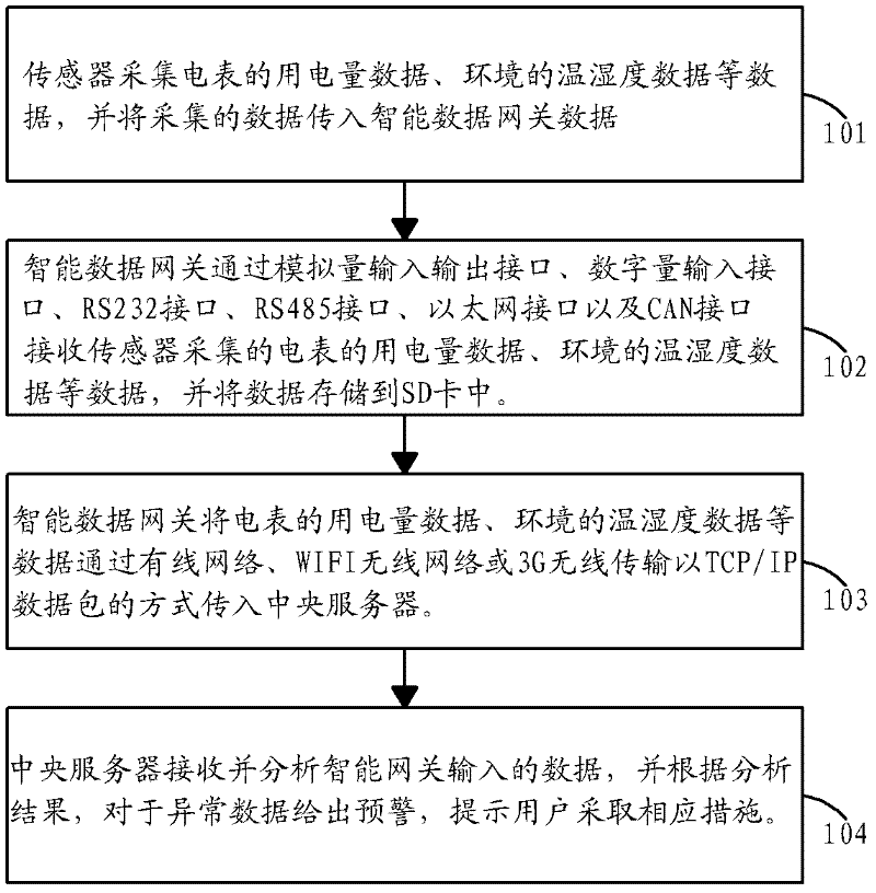
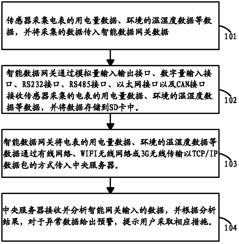
[0029] The present invention will be further described below in conjunction with drawings and embodiments. Please refer to figure 1 as shown, figure 1 It is a flow chart of the monitoring method of the energy power environment of the present invention.

[0030] In this embodiment, a method for monitoring an energy and power environment, the method includes the following steps:

[0031] Step 101, the sensor collects relevant operating data of the electrical equipment, and transmits the collected data to the data gateway. The sensors include front-end ammeter sensors, temperature and humidity sensors, and equipment status sensors; the relevant data of the electrical equipment includes power consumption data of the electrical meter, environmental temperature and humidity data, and status data of the electrical equipment. The data gateway is an intelligent data gateway.

[0032] Step 102, the intelligent data gateway receives and stores the relevant operating data of the elect...


PUM


Abstract

The invention discloses an energy dynamic environment monitoring method, which is applied to the field of energy dynamic environment monitoring. Related operation data of electric equipment are collected through a sensor, the collected data are sent to a data gateway, and the data gateway receives and stores the related operation data of the electric equipment and then enables the related operation data to be sent to a central server. The central server receives and analyzes the related operation data of the electric equipment, gives warning to abnormal data according to analysis results, and prompts users to take corresponding measures. The energy dynamic environment monitoring method can find and process the abnormal data in time, completes real-time monitoring of energy environment of the electric equipment and is high in monitoring efficiency and small in workload of machine room management personnel.

Description

technical field [0001] The invention relates to the monitoring field of energy and power environment, in particular to a method and system for monitoring the energy and power environment. Background technique [0002] my country's energy utilization efficiency is only 30%, which is about 10% lower than that of developed countries. my country's per capita energy consumption is only 50% of the world average, but energy consumption per unit of output is 2.5 times the world average, four times that of Europe and the United States, and seven times that of Japan. The market size of the global energy-saving and environmental protection industry has increased from 250 billion US dollars in 1992 to 600 billion US dollars last year; the Chinese government has taken the energy-saving and environmental protection industry as an important support for the development of green economy, low-carbon economy and circular economy. In 2000, the total output value of my country's energy-saving an...

Claims


Application Information

Patent Timeline
Patent Type & Authority Applications(China)
IPC IPC(8): H04L12/24H04L29/08
Inventor 王芳
Owner WUXI GANGWAN NETWORK TECH
Why Eureka
Try Eureka