Shaker-type transducer with centering device

A vibrator and transducer technology, applied in the direction of sensors, electrical components, etc., can solve problems such as low stretchability, and achieve the effects of optimized use, economic benefits, and cheap components

Active Publication Date: 2012-06-13
ASK IND SPA
View PDF13 Cites 8 Cited by
  • Summary
  • Abstract
  • Description
  • Claims
  • Application Information

AI Technical Summary

Problems solved by technology

Therefore, the vibrator / exciter has relatively low stretchability

Method used


Image

  • Shaker-type transducer with centering device
  • Shaker-type transducer with centering device
  • Shaker-type transducer with centering device

Examples


Embodiment Construction

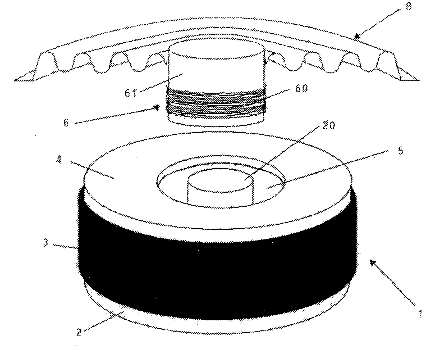
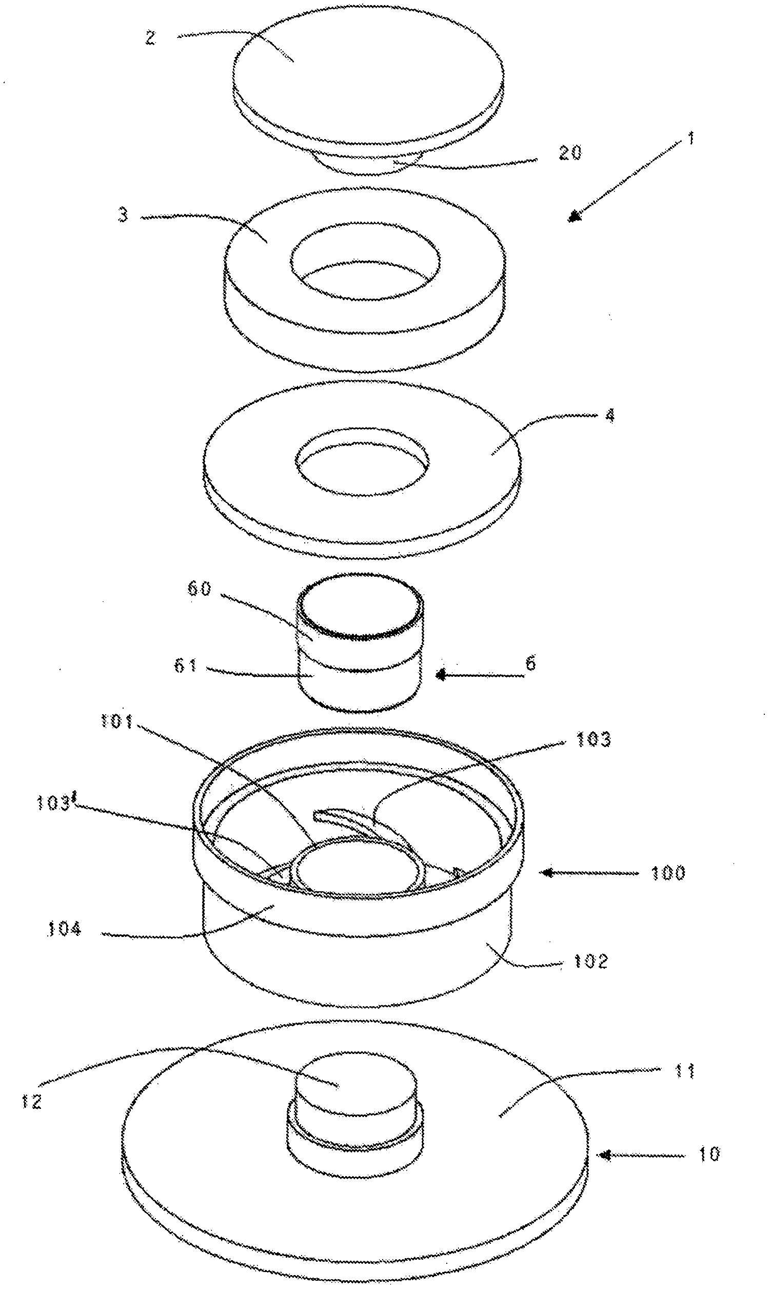
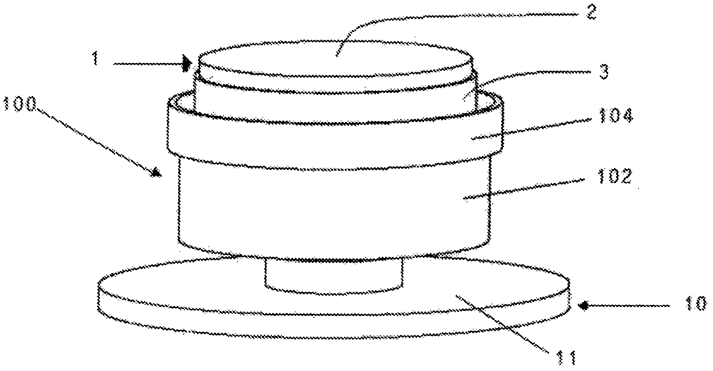
[0060] now refer to Figure 2-6 , discloses a centering element according to the invention, generally indicated by the numeral (100).

[0061] The centering element (100) comprises a central cylindrical rod (101) adapted to be fixed to the cylindrical support (61) of the voice coil (6), for example by glue.

[0062] A plurality of spokes (103, 103') branching out from the central cylindrical rod (101), having a thickness less than the length of the central cylindrical rod, is more flexible.

[0063] The spokes (103, 103') are attached to the inner surface of the peripheral cylindrical rod (102). The peripheral cylindrical rod (102) is longer than the central cylindrical rod (101).

[0064] The peripheral cylindrical rod (102) is provided with an annular flange (104) having a larger diameter than the peripheral rod, adapted to be fixed to the second plate (4) of the transducer, for example by glue .

[0065] Advantageously, a self-centering system can be arranged between th...


PUM


Abstract

A shaker transducer is disclosed, which comprises a magnetic unit (1) composed of a magnet (3) disposed between a first polar plate (2) and a second polar plate (4) in such a way to generate a toroidal air gap (5). A sound coil (6) is disposed in the air gap (5) to move axially and a centering element (100) is fixed to the coil to maintain it centered with respect to the magnetic unit (1). A rigid element (10) comprising a shank (12) fixed to said cylindrical support (61) of the sound coil and adapted to be anchored to a surface to transfer the sound vibrations generated by the magnetic unit (1). The centering element (100) comprises a central cylindrical shank (101) fixed to the coil, a peripheral shank (102) fixed to the second polar plate (4) and a plurality of elastic spokes (103, 103') disposed between said central shank (101) and said peripheral shank (102).

Description

technical field [0001] The present patent application for industrial invention relates to a magnetodynamic transducer of the vibrator or exciter type with an improved centering system of the moving coil. Background technique [0002] Referring to FIG. 1 , a magnetodynamic transducer according to the prior art is disclosed. The transducer includes a magnetic unit, generally indicated by the numeral (1). [0003] The magnetic unit (1) includes a permanent magnet (3), usually ferrite, which is ring-shaped and arranged between the first pole plate (2) and the second pole plate (4). The second pole plate (4) is annular similar to the permanent magnet (3); the first pole plate (2) has a pole center (20), which is suitable for being inserted into the hole of the magnet and the second pole plate with a certain gap , thus forming an annular space called the air gap (5). [0004] Although ring magnets (3) (usually ferrite) are illustrated in the drawings, the magnetic unit (1) can ...

Claims


Application Information

Patent Timeline
Patent Type & Authority Applications(China)
IPC IPC(8): H04R9/06H04R9/04
CPCH04R9/043H04R9/066
Inventor C·桑奇西A·法尔乔尼
Owner ASK IND SPA
Why Eureka
Try Eureka