
Laser bird repelling device and laser bird repelling method

A bird repellent and laser technology, applied in animal repellent, application, animal husbandry, etc., can solve the problems of small effective range, easy adaptability of birds, and endangering flight safety

Inactive Publication Date: 2012-06-20
BEIJING YOTAISC SCI & TECH DEV
View PDF10 Cites 9 Cited by
  • Summary
  • Abstract
  • Description
  • Claims
  • Application Information

AI Technical Summary

Problems solved by technology

[0005] The bird repelling equipment that scares the bird's sense of hearing has a small effective range, produces loud noises to the airport environment, and the birds are prone to adaptability; the method of stimulating birds through the sense of smell, because the airport area is huge, and the stimulating drugs last The time is very short, the species of stimulating birds are limited, etc., so it is not very practical; killing birds may also endanger flight safety, it is not a green and ecological bird repelling method, and it is not applicable under low light conditions at night; ecological bird prevention and Bird detection radar is still immature, and can only reduce the possibility of birds entering the airport, and does not have the effect of direct bird repelling; the traditional visual bird repelling method is single, the means are low in technical content, and the intensity of light used to stimulate birds low, so the effect is not significant
[0006] The problems that bird repellent equipment needs to solve urgently are: to solve the adaptability of birds, to solve the problem of bird repelling under low light and low altitude conditions, to solve the problem of short effective time, large range of action and high cost, so as to make bird repellent move toward artificial intelligence and high-tech bird repellent

Method used


Image

  • Laser bird repelling device and laser bird repelling method
  • Laser bird repelling device and laser bird repelling method
  • Laser bird repelling device and laser bird repelling method

Examples


Embodiment Construction

[0029] It should be noted that, in the case of no conflict, the embodiments in the present application and the features in the embodiments can be combined with each other. The present invention will be described in detail below with reference to the accompanying drawings and examples.

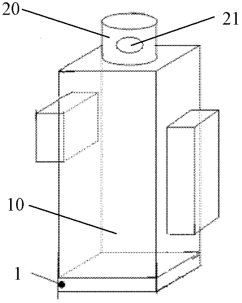
[0030] figure 1 A schematic diagram of the external structure of an embodiment of the laser bird repeller according to the present invention is shown. Such as figure 1 As shown, it can be seen from the figure that the laser bird repeller of this embodiment includes: a box body 10, a turret 20, a laser emitting unit and a controller. Wherein, the turret 20 is pivotably arranged on the box body 10, and the turret 20 has a transparent window 21; the laser emitting unit is arranged in the box body 10, and the laser emitting unit forms a laser scanning beam from the transparent window 21 Exited for scanning, the laser scanning beam scans towards below the horizontal plane; the controller is used ...


PUM


Abstract

The invention provides a laser bird repelling device and a laser bird repelling method, wherein the laser bird repelling device comprises a box body (10), a rotating tower (20) capable of being arranged on the box body in pivot rotation mode, a laser emitting unit arranged in the box body (10) and a controller. A transparent window (21) is arranged on the rotating tower (20), the laser emitting unit generates laser scanning beams through a laser source and emits the laser scanning beams from the transparent window for scanning, and the laser scanning beams scan toward downside of the horizontal plane. The controller is used for controlling the laser source. The laser bird repelling device fills the blank in bird repelling measures under low light and low altitude conditions, and can effectively repel birds on a runway and / or a grass land. Simultaneously, the laser scanning beams scan toward the downside of the level, so that visual lines of a pilot cannot be hampered, and flying safety can be guaranteed.

Description

technical field [0001] The invention relates to the technical field of laser bird repellent, in particular to a laser bird repellent device and a laser bird repellent method. Background technique [0002] From 1990 to 2010, the direct economic loss caused by bird strikes in China's civil aviation was about 850 million yuan, and the average annual loss was about 40 million yuan, of which the direct economic loss in 2010 was about 140 million yuan. Indirect losses caused by attacks, such as flight delays or cancellations, personnel safety, etc. [0003] The current bird repelling methods are divided into hearing (such as gas cannons, bird repelling vehicles, firecracker launchers, etc.), vision (such as scarecrows, colorful wind wheels, horror eyes, laser bird repelling, etc.), smell (such as bird repellents, ammonia water, etc.) , pesticides, etc.), hunting (such as shotguns, sticky bird nets, etc.), ecology (mowing, insecticide), and bird detection radar systems for early w...

Claims


Application Information

Patent Timeline
IPC IPC(8): A01M29/10
Inventor 田刚印
Owner BEIJING YOTAISC SCI & TECH DEV
Learn More