Optical fiber angle sensor for measuring structural angles

An angle sensor and optical fiber technology, applied in the field of optical sensors, can solve the problems of increased control difficulty, susceptibility to interference, failure to meet requirements, etc., and achieve the effect of improving sensitivity

Inactive Publication Date: 2014-04-16
NORTHWESTERN POLYTECHNICAL UNIV
View PDF4 Cites 0 Cited by
  • Summary
  • Abstract
  • Description
  • Claims
  • Application Information

AI Technical Summary

Problems solved by technology

Although this EMG sensor method can ensure the real-time performance of signal acquisition, the biggest disadvantages of EMG sensors were found during the experiment: 1) It is easy to fall off and shift under intense exercise; 2) After long-term exercise, Human body sweating will affect the sensor measurement; 3) There are certain differences in the sensor with different individuals; 4) The sensor must be attached to the surface of the human body every time, which is inconvenient to use; interference, which makes it more difficult to control
At present, the existing optical fiber sensor structure with notch mainly adopts zigzag continuous notch. This structure is mainly used for the deformation curvature measurement of the structure, and its accuracy for the curvature measurement of the micro-region structure is high. The design method, the length of the modulation area is generally very small, only within 5mm, if the length of the modulation area is too long, the signal at the output end will be very weak, and the measurement purpose cannot be achieved
Therefore, it is used for the measurement of large structural angles in the transition zone, such as the knee joint angle of the human body, and its measurement range will be very small, which cannot meet the requirements

Method used


Image

  • Optical fiber angle sensor for measuring structural angles

Examples


Embodiment Construction

[0014] Describe the present invention below in conjunction with specific embodiment:

[0015] This embodiment is an optical fiber angle sensor applied to a joint of an exoskeleton robot to measure the angle of a human joint. In this embodiment, the optical fiber angle sensor is installed at the knee joint of the human body.

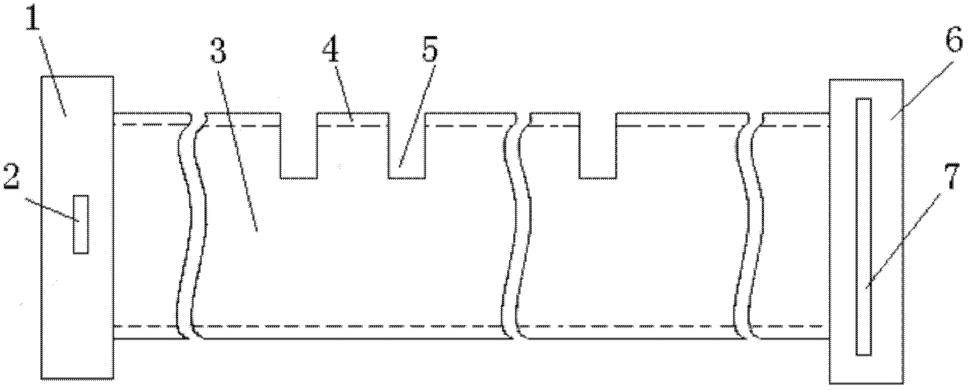
[0016] The fiber optic angle sensor in this embodiment includes a special optical fiber, a light emitting component 2 and a light receiving component 7 . The special optical fiber is in the shape of a wire. The special optical fiber includes a special optical fiber core 3 and a special optical fiber cladding 4. The diameter d1 of the special optical fiber core is 100 microns, and the outer diameter d2 of the special optical fiber cladding is 140 microns. The special optical fiber core is made of thermosetting acrylic resin The special optical fiber cladding is made of fluororesin (PEP) and integrally formed with the special optical fiber core.

[0017] ...


PUM


Abstract

The invention provides an optical fiber angle sensor for measuring structural angles, which comprises a purpose-made optical fiber, a light transmitting component and a light receiving component. N perpendicular rectangular grooves are uniformly arranged on the optical fiber, and a light absorption material is coated on the inner surface of each rectangular groove; the section of each rectangular groove is circular-crown-shaped, the range of the largest depth h of each rectangular groove is larger than d2-d1 and smaller than d2 / 2, the surface roughness Ra of each rectangular groove is required to be smaller than or equal to 0.05, and the range of the pitch s2 between each two adjacent rectangular grooves is larger than 5(h+d1-d2); and a light intensity modulation area is formed on the purpose-made optical fiber between the first rectangular groove and the Nth rectangular groove, and the axial length of the light intensity modulation area is not larger than 5cm. When the purpose-made optical fiber deflects by an angle along with a structure, a part of light is absorbed by a light absorbing layer when the light passes through the rectangular grooves of the light intensity modulation area, the light intensity of the absorbed light is increased along with reduction of a structural angle, the light intensity of the light received by the light receiving component is changed obviously along with the angle, and accordingly sensitivity of the sensor to the structural angle is improved.

Description

technical field [0001] The invention relates to the technical field of optical sensors, in particular to an optical fiber angle sensor for measuring structure angles. Background technique [0002] Exoskeleton robots are autonomous machines that attach to the human body to help people carry weight. An important feature of the exoskeleton robot is that it captures the movement intention or behavior of the human body through the sensors installed on the human body, and uses this as a control signal to drive and control the exoskeleton so that it can walk synchronously with the user. At present, the research on exoskeleton robots in the world is at the forefront of the HybridAssistive Leg (HAL) developed by Cybernics of the University of Tsukuba, Japan, and the "Berkeley lower extremity exoskeleton (BLEXE)" (Berkeley lower extremity exoskeleton, BLEXE) developed by the Robotics and Human Engineering Laboratory of the University of California, Keley. ). They all use myoelectric...

Claims


Application Information

Patent Timeline
Patent Type & Authority Patents(China)
IPC IPC(8): A61B5/103G01B11/26
Inventor 张小栋张振海贾丙辉杜玉环
Owner NORTHWESTERN POLYTECHNICAL UNIV
Why Eureka
Try Eureka