Cutting head

A cutting head and lens technology, applied in welding equipment, laser welding equipment, metal processing equipment, etc., can solve the problems of difficult to accurately determine the initial point of cutting, cumbersome and complicated operation, and increase the actual load of the mechanical arm, so as to ensure the cutting quality and Stability, convenient and fast operation, and the effect of improving machining accuracy

Active Publication Date: 2012-06-20
CHERY AUTOMOBILE CO LTD
View PDF8 Cites 15 Cited by
  • Summary
  • Abstract
  • Description
  • Claims
  • Application Information

AI Technical Summary

Problems solved by technology

The existing domestic laser cutting heads generally have the following defects: First, it is difficult to achieve rapid adjustment in the Z-axis direction. When the thickness of the workpiece to be processed changes, it is often necessary to adjust the relative height of the mechanical arm connected to the laser cutting head. The operation is cumbersome and complicated, which brings great troubles to the staff; secondly, there is a problem in the adjustment of the focus spot of the cutting head, because after the parts of the cutting head are processed and installed, there is an accumulation of errors, or the actual emission of light in the cutting head There is a deviation between the angle and the axis of the focusing head assembly of the cutting head, or the relative position of the focal point of the output laser focus spot and the workpiece, which will affect the actual processing effect at the slightest, and cause the focusing head assembly to overheat and burn due to the obstruction of the optical path. This greatly increases the maintenance cost of the manufacturer; finally, before the actual processing, the laser cutting head is manually measured and installed according to the staff to determine the initial point of laser cutting. It greatly affects the quality of the final product; finally, the existing cutting head is often bulky, difficult to transport and install, and also greatly increases the actual load of the mechanical arm, which consumes a lot of energy

Method used


Image

  • Cutting head
  • Cutting head
  • Cutting head

Examples


Embodiment Construction

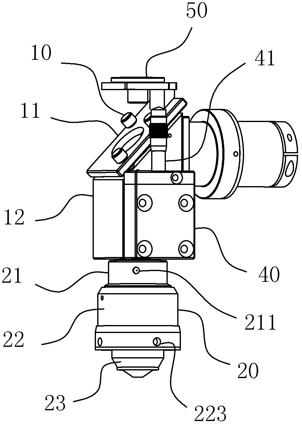
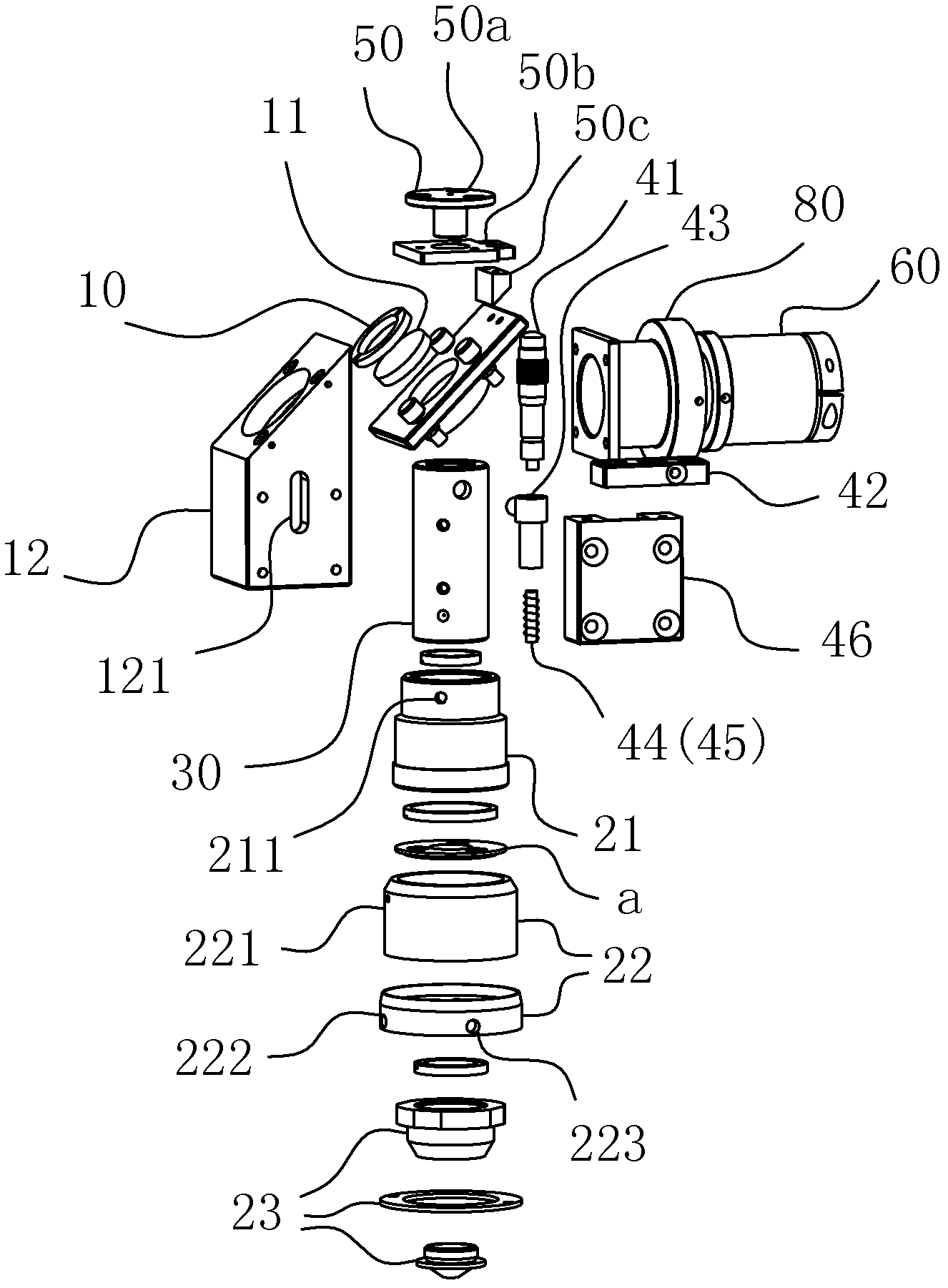
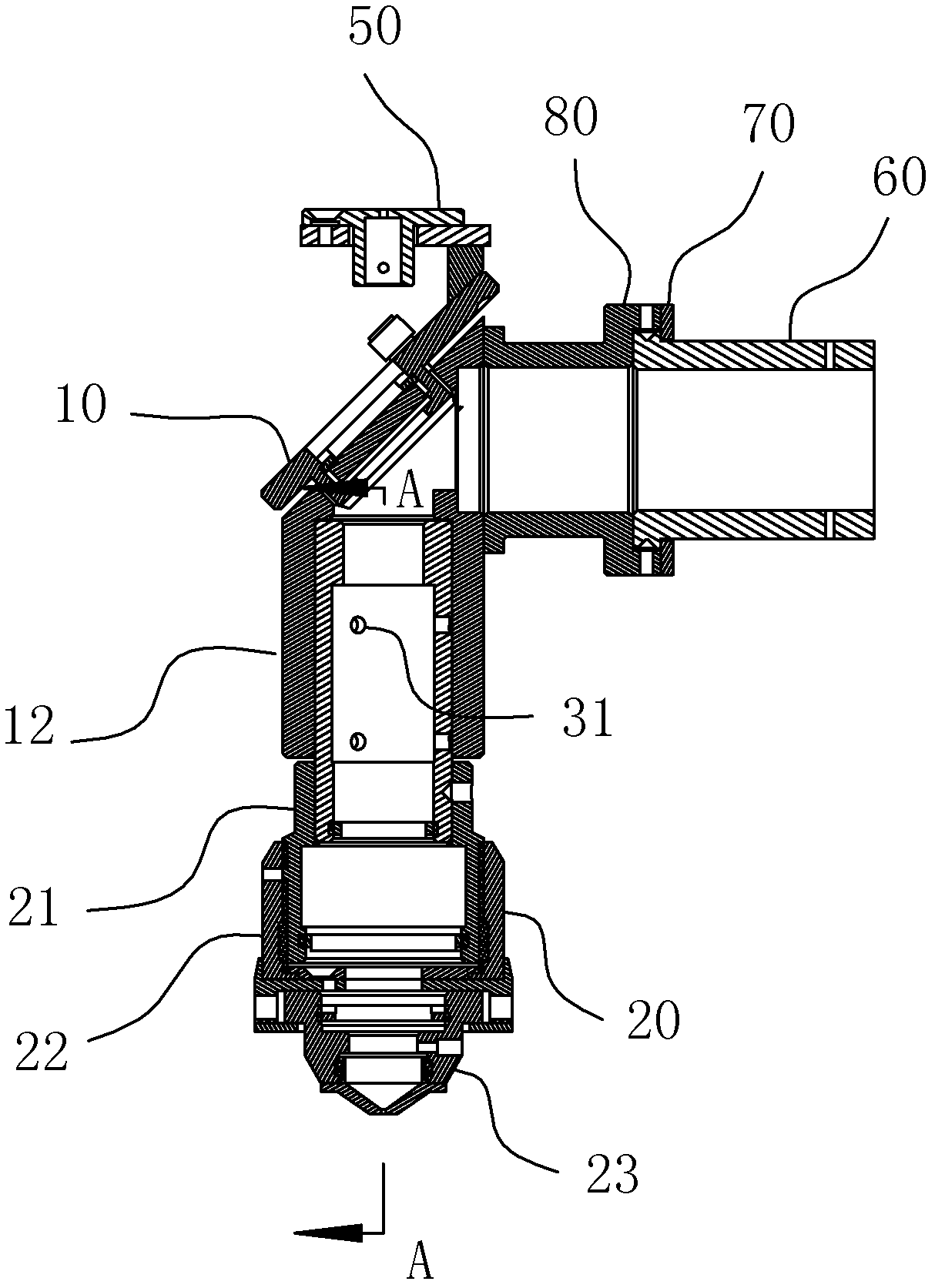
[0010] A cutting head, comprising an optical path entrance lens, an optical path exit lens, and a reflector assembly 10 for reflecting the light path. The main light beam enters the optical path entrance lens, is reflected by the reflector assembly 10, and then exits through the optical path exit lens. The optical path exit lens includes Focusing head assembly 20, the cutting head also includes an adjustment mechanism 40 that can be used to make the focusing head assembly move along the Z-axis direction, such as Figure 1-2 as well as Figure 4 shown.

[0011] In the actual processing of the laser cutting machine, the workpiece to be processed is laid horizontally on the processing plane of the laser cutting machine, and the output optical path of the cutting head is set perpendicular to the workpiece, which is the above-mentioned Z-axis setting. When it is necessary to adjust the distance between the cutting head and the battery plate, the Z-axis adjustment mechanism arrange...


PUM


Abstract

The invention belongs to the field of laser machining, and particularly relates to a cutting head, which is used for laser fine cutting and comprises a light path incident lens, a light path emergent lens, a reflector component and an adjusting mechanism. The reflector component is used for reflecting light paths, main light enters the cutting head via the light path incident lens and exits the cutting head via the light path emergent lens after being reflected by the reflector component, the light path emergent lens consists of a focusing head component, and the adjusting mechanism can be used for driving the focusing head component to move along a Z-axis direction. When the thickness of a machined workpiece is changed, the purpose of accurately controlling the position of a focal point of the focusing head component can be directly achieved by means of adjusting the Z-axis adjusting mechanism positioned in a cutting head body, high energy of laser within a focal depth range can be sufficiently utilized, machining precision is improved, and accordingly the quality and the stability of cutting of the workpiece are eventually guaranteed. In addition, the cutting head is more convenient and speedy in operation as compared with a traditional laser cutting head troublesome in operation due to the fact that the relative height of a mechanical arm connected with the traditional laser cutting head needs to be integrally adjusted.

Description

technical field [0001] The invention belongs to the field of laser processing, and in particular relates to a cutting head for fine laser cutting. Background technique [0002] The laser cutting machine uses the laser beam emitted from the laser generator to be focused into a high-power-density laser beam to irradiate the workpiece through the laser cutting head. The laser heat is absorbed by the workpiece material, and the temperature at this point of the workpiece rises sharply and reaches the boiling point. The material begins to vaporize and form holes, and as the beam moves relative to the workpiece, the material eventually forms a slit in the corresponding place. Among the various parts of the laser cutting machine, the reasonable selection of the cutting head is very important for the quality of the final laser cutting. The existing laser cutting head consists of an optical path incident device, a mirror assembly for reflecting light and a focusing head assembly for ...

Claims


Application Information

Patent Timeline
Patent Type & Authority Applications(China)
IPC IPC(8): B23K26/04B23K26/38B23K26/02
Inventor 徐海峰
Owner CHERY AUTOMOBILE CO LTD
Why Eureka
Try Eureka