Blow molding device and blow molding method thereof

A technology of blow molding and products, which is applied in the fields of blow molding, blow molding devices, and liquid-cooled blow molding devices of the above-mentioned blow molding devices, and can solve problems such as slow cooling speed and poor surface quality of products. Accelerate the cooling rate and improve the surface quality

Inactive Publication Date: 2017-03-29
倪美琴
View PDF6 Cites 0 Cited by
  • Summary
  • Abstract
  • Description
  • Claims
  • Application Information

AI Technical Summary

Problems solved by technology

[0004] The cooling method of the existing blow molding machine is through air cooling, and its defect is that the cooling speed is slow; at the same time, because the air cooling takes a long time, the surface quality of the product is not good

Method used


Image

  • Blow molding device and blow molding method thereof
  • Blow molding device and blow molding method thereof
  • Blow molding device and blow molding method thereof

Examples


Embodiment 1

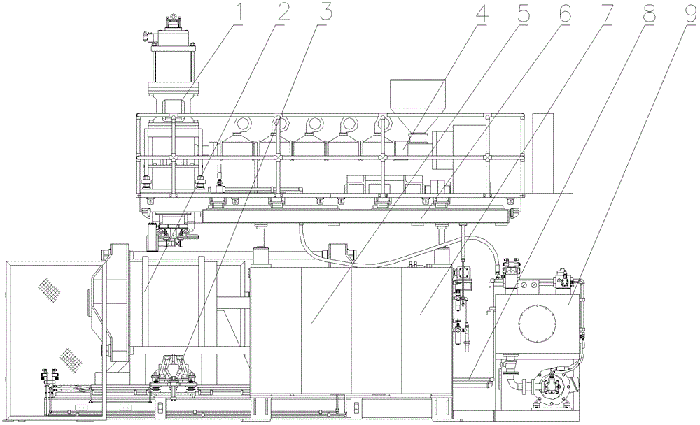
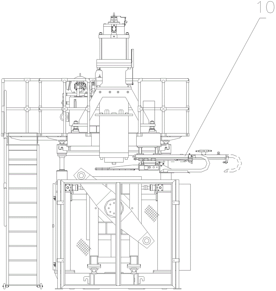
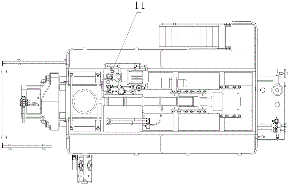
[0043] see Figure 1 to Figure 3 , the present invention discloses a blow molding device, comprising: a frame 6, an extrusion mechanism 4, a die head 1, a mold clamping mechanism 2, a blow down mechanism 3, a manipulator 10, a controller (including an electrical system 5, a pneumatic system 7. Hydraulic system 9), pipeline system 8, hydraulic servo power supply 11. The controller is respectively connected to the extrusion mechanism 4, the die head 1, the mold clamping mechanism 2, the blow down mechanism 3, and the manipulator 10 to control the extrusion mechanism 4, the die head 1, the mold clamping mechanism 2, the blow down mechanism 3, The manipulator 10 cooperates.

[0044] The frame 6 is mainly composed of pillars and frame-shaped beams to support the manipulator 10 and the die head 1. The pillars are formed columnar members, the bottom end of which is provided with a flange for fixed connection with the common base, and the top end is used to support the frame-shaped B...

Embodiment 2

[0064] The difference between the blow molding device of this embodiment and Embodiment 1 is that in this embodiment, if Figure 5 As shown, the blow molding product is flat; the water delivery pipe is arranged at the bottom of the blow molding product, and the exhaust hole 14 is arranged at the upper part of the blow molding product.

[0065] The difference between the blow molding method of this embodiment and Embodiment 1 is that in this embodiment, in the step S5, the closed space of the blow-molded product is filled with liquid, and the top of the blow-molded product is provided with an exhaust hole 14; After the blow-molded product is cooled, the liquid in the blow-molded product is discharged through step S6.

[0066] In summary, the blow molding device and blow molding method proposed by the present invention have changed the existing cooling method, and after the product is basically formed, the thin-walled product is cooled by liquid cooling, so as to speed up the co...


PUM


Abstract

The invention discloses a blow molding device and its blow molding method. The blow molding device comprises a frame, an extrusion mechanism, a die, a clamping mechanism, a lower blowing mechanism, manipulators and a controller. The clamping mechanism comprises at least two clamping units each of which is provided with a first guide rail for leading movement of the clamping unit; the blow molding device also comprises a second guide rail for leading movement of the manipulators, wherein the second guide rail is perpendicularly arranged relative to the first guide rail; after clamping, pipe billets cling to the clamping mechanism under action of windpower blown from the lower blowing mechanism, and a closed space is formed in the blow molding products; the device also comprises a low temperature liquid spraying mechanism one end of which is communicated with the closed space of the blow molding product for cooling the blow molding product after blow molding the products by spraying low temperature liquid. The invention changes the existing cooling style and the liquid cooling mode is adopted in the invention for cooling the thin wall products after the products are basically molded, quickens the cooling speed and raises the surface quality of products.

Description

technical field [0001] The invention belongs to the technical field of blow molding, and relates to a blow molding device, in particular to a liquid-cooled blow molding device; meanwhile, the invention also relates to a blow molding method for the blow molding device. Background technique [0002] The existing blow molding machine mainly includes a frame, an extrusion mechanism, a die head, a mold clamping mechanism, and a blowing mechanism. Its working method is: after the liquid plastic is sprayed out, the plastic body is blown onto A mold cavity of a certain shape is made into a product. The plastic is melted and extruded quantitatively in the screw extruder, then formed by laminating the film, and then cooled by blowing through the air ring, and then pulled by a tractor at a certain speed, and wound into a roll by a winder. [0003] For example, Chinese patent CN 200610119347.3 discloses a stretch blow molding method for container bottles. The molten resin preform is se...

Claims


Application Information

Patent Timeline
Patent Type & Authority Patents(China)
IPC IPC(8): B29C49/04B29C49/66B29C49/78
Inventor 倪美琴
Owner 倪美琴
Why Eureka
Try Eureka