Method for manufacturing plastic pipe flange connectors by pressing and sintering

A flange joint and plastic pipe technology, applied in the field of plastic processing, can solve problems such as uneven heating, accelerated nozzle wear, and low flange strength, and achieve the effects of convenient installation and use, guaranteed butt joint accuracy, and high connection strength

Inactive Publication Date: 2012-06-20
CHANGDE NEMET ENG POLYMERS MATERIALS +1
View PDF4 Cites 1 Cited by
  • Summary
  • Abstract
  • Description
  • Claims
  • Application Information

AI Technical Summary

Problems solved by technology

[0002] The flanging flange connection of plastic pipes is generally a metal flange that turns the nozzle outward to form an annular step at the port to block the inner movement, or directly uses the annular step itself as a flange (but the flange strength is low), through the method Lan connects the pipes
This connection method is very difficult to construct when processing large-diameter thick-walled pipes. It is not easy to roll up the pipe mouth, and the heating is not uniform when rolling up. The plastic is easy to oxidize or burn, and the quality of the flanging cannot be strictly controlled.
The unevenness of the flanging port and the circular arc between the inner diameter of the port and the flanging will cause the sealing of the connecting pipe to be loose, and the flowing medium will form a vortex here, which will accelerate the wear of the nozzle
The flanging and the movable metal flange are not a whole. When the pipes are connected, the end faces of the pipes cannot be completely matched with each other, forming a step, which will also cause serious wear on the nozzle.

Method used


Image

  • Method for manufacturing plastic pipe flange connectors by pressing and sintering
  • Method for manufacturing plastic pipe flange connectors by pressing and sintering

Examples


Embodiment Construction

[0016] The present invention is described in detail as follows in conjunction with accompanying drawing:

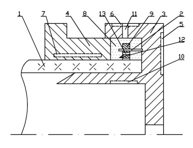
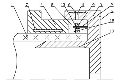
[0017] This press-sintering method is used to make plastic pipe flange joints. A mold assembly is installed at the end of the plastic pipe, and resin materials of the same material as the plastic pipe are added to the mold cavity formed by the mold assembly, and then pressurized at both ends of the mold. Form the flange preform, and turn on the temperature-controllable heating device at the same time to fully melt the added material, pressurize and keep it for a certain period of time, cut off the heating power supply, and disassemble the mold after cooling to form a flange.

[0018] exist figure 1 Among them, the mold assembly is composed of bottom mold 3, sliding mold 4 and heaters 5, 6, 7, 10. The bottom mold 3 is two concentric cylinders with different sizes of the inner core and the jacket, the inner core is 2° guide taper, the outer diameter of the inner core...


PUM

PropertyMeasurementUnit
lengthaaaaaaaaaa
thicknessaaaaaaaaaa

Abstract

The invention discloses a method for manufacturing plastic pipe flange connectors by pressing and sintering. An upper die component is installed at an end part of a plastic pipe; resin material, which is the same as that of the plastic pipe, is added into a cavity where a die component is formed; then two ends of the die are compressed to form flange preforms; a temperature-controlled heating device is simultaneously started, so as to ensure that the material added is sufficiently molten; compressing and heat preservation are performed for a certain period of time, then a heating power supplyis cut off; and the die is disassembled after being cooled, and then a flange is formed. The special die adopted in the method has a simple structure and is convenient to install and use, and by adopting the heating and compressing forming method, molten powder material completely covers the embedded metal flange and is organically combined with the pipe into a whole body. The connection mode hasthe characteristics that the connection strength is high, the butt accuracy of end surfaces of the flange is guaranteed, and construction is convenient.

Description

technical field [0001] The invention relates to plastic processing, that is, a pressing-sintering method for making flange joints of plastic pipes. It is suitable for directly forming flange joints at the ends of various thermoplastic pipes, especially for flange joints of ultra-high molecular weight polyethylene or polytetrafluoroethylene pipes with poor processability. Background technique [0002] The flanging flange connection of plastic pipes is generally a metal flange that turns the nozzle outward to form an annular step at the port to block the inner movement, or directly uses the annular step itself as a flange (but the flange strength is low), through the method Lan connects the pipes. This connection method is very difficult to construct when processing large-diameter thick-walled pipes. It is not easy to turn the nozzle, and the heating is not uniform when rolling, the plastic is easy to oxidize or burn, and the quality of the flanging cannot be strictly control...

Claims


Application Information

Patent Timeline
Patent Type & Authority Applications(China)
IPC IPC(8): B29C69/02B29C33/00B29C33/76B29C33/42
Inventor 蒋宏罗雄
Owner CHANGDE NEMET ENG POLYMERS MATERIALS
Why Eureka
Try Eureka