
Position correction device

A calibration and uniform technology, applied in the field of calibration devices, can solve problems affecting product quality, easy cracking, falling, etc., achieve the effect of smooth workpiece conveying process, and improve accuracy and efficiency

Active Publication Date: 2012-06-20
GUANGDONG HOMEWAY CERAMICS IND +1
View PDF6 Cites 4 Cited by
  • Summary
  • Abstract
  • Description
  • Claims
  • Application Information

AI Technical Summary

Problems solved by technology

[0004] In addition, when the glaze layer on the edge of the adobe is in contact with the baffle or the synchronous belt, it is easy to crack and fall off, especially when producing special-shaped adobes with flat edges or special brick adobes with a large surface and a small bottom, this phenomenon is more serious. greatly affect the quality of the product

Method used


Image

  • Position correction device
  • Position correction device
  • Position correction device

Examples


Embodiment Construction

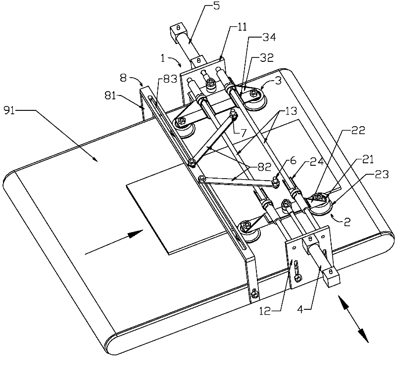
[0030] Figure 3-5 The brick correction device shown is an embodiment of the present invention, which includes a support 1, two sets of stoppers 2, 3 oppositely arranged, two sets of electric eyes 6, 7 for sensing the position of the workpiece, and a control system (not shown) And adjusting frame 8.

[0031] Wherein, the bracket 1 includes two installation side plates 11, 12 and more than two connecting guide rods 13 arranged parallel and horizontally.

[0032] The two groups of stoppers 2 and 3 have the same structure, taking the stopper 2 as an example: it includes two identical wheels 21 and mounting frames 22, and the two wheels 21 are arranged in a row and are rotatably mounted on the corresponding mounting frames 22 On the top, the axes of the two wheels 21 are set vertically; the two wheels 21 are respectively fixedly covered with a protective cover 23, and the protective cover 23 is composed of a lower part with a larger outer diameter and an upper part with a smaller...


PUM


Abstract

The invention relates to a position correction device which is characterized by comprising a bracket and two groups of stop pieces arranged oppositely, wherein the two groups of stop pieces are horizontally and movably arranged on the bracket, connected with power sources respectively and respectively driven by the corresponding power sources to move in the same direction or opposite directions; at least two transversely distributed contact pivots are arranged on the opposite sides of the two groups of stop pieces respectively; a working surface is composed of a plurality of contact pivots of the same group of a stop piece; and the working surfaces of the two groups of stop pieces are vertical to the moving directions of the two groups of stop pieces. The two groups of stop pieces move in the same direction or opposite directions, and the respective stop pieces are provided with the plurality of contact pivots to form the working surfaces; when the corresponding stop piece pushes a workpiece, the friction between the stop piece and the workpiece is dispersed at a plurality of positions on the side surface of the workpiece; when pushing the workpiece to translate, the stop piece can continuously adjust the direction of action on the workpiece; and the stop pieces on two sides work circularly, so that the workpiece can reach a corrected position accurately, and is smoothly conveyed to a glazing wire belt, therefore, the workpiece at the corrected position can be conveyed smoothly.

Description

Technical field [0001] The invention relates to a calibration device, in particular to a calibration device capable of parallel pushing and adjusting the parallel offset of workpieces, so that the workpieces are arranged neatly and conveyed smoothly; the invention is especially suitable for roller printing machines and Workpieces transferred between glaze lines are calibrated. Background technique [0002] In the ceramic industry, with the popularization of roller printing machines, various manufacturers will face a problem, that is, the rubber rollers of roller printing machines are longer. When printing, in order to ensure the richness of printed product patterns and extend the use of rubber rollers Generally, a swing machine is used before the roller printing machine, so that the printed bricks can be printed at different parts of the effective length of the roller, and the width of the two conveyor belts of the glaze line is designed according to the specifications of th...

Claims


Application Information

Patent Timeline
Patent Type & Authority Applications(China)
IPC IPC(8): B65G47/26
Inventor 梁桐灿余明国
Owner GUANGDONG HOMEWAY CERAMICS IND
Learn More