
Scraping plate mixing and stirring sand removing device

A mixing and stirring, scraper type technology, applied in mixers, feed/discharge devices of sedimentation tanks, mixers with rotary stirring devices, etc. , manual removal and other problems, to achieve the effect of simple structure, convenient use and stable biogas

Inactive Publication Date: 2012-06-20
滕州市百润机械科技有限公司
View PDF3 Cites 7 Cited by
  • Summary
  • Abstract
  • Description
  • Claims
  • Application Information

AI Technical Summary

Problems solved by technology

The sand content in the raw material is very important to the production of biogas. The sand enters the anaerobic fermentation tank along with the raw material. Since the sand is not easy to be discharged with the biogas residue due to its weight, it will deposit at the bottom of the anaerobic fermentation tank and accumulate more and more over time. The more it takes up the volume of the anaerobic fermentation tank, it not only affects the feed amount and gas production rate, but also requires manual removal, which is very troublesome
First, release the 1000 ~ 8000m in the tank 3 The raw materials need to be ventilated in the tank to prevent methane poisoning of the sand cleaners. After the sand is cleared, the production needs to be re-cultivated and inoculated again, which is very troublesome and takes a long time.

Method used


Image

  • Scraping plate mixing and stirring sand removing device
  • Scraping plate mixing and stirring sand removing device
  • Scraping plate mixing and stirring sand removing device

Examples


Embodiment Construction

[0019] The present invention will be further described below in conjunction with accompanying drawing and specific embodiment:

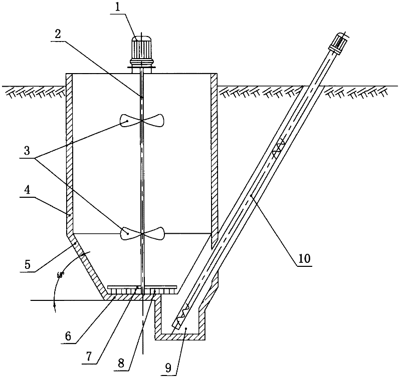
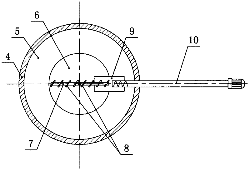
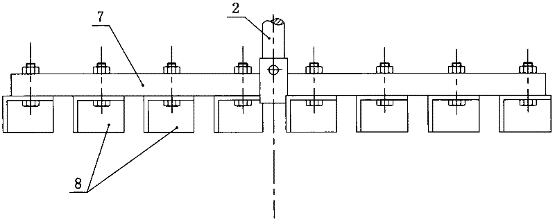
[0020] A scraper type mixing and stirring desanding device, such as figure 1 , figure 2 , image 3 , Figure 4 As shown, it includes a mixing pool 4, a cone bucket 5 is connected to the bottom of the mixing pool 4, a rotating vertical shaft 2 is arranged in the mixing pool 4 and the cone bucket 5 for relative rotation, the upper end of the rotating vertical shaft 2 is connected to a motor 1, and the rotating vertical shaft 2 is fixedly installed There are stirring paddles 3, the lower end of the cone bucket 5 has a pool bottom 6, and one side of the pool bottom 6 is provided with a sand pit 9, which is connected to the cone bucket 5, and the bottom wall of the sand pit 9 is at a lower altitude than the bottom of the pool 6 altitude, sand conveyor 10 is provided in the sand pit 9, the bottom of the sand conveyor 10 is located in the sand pit 9, an...


PUM


Abstract

The invention relates to a scraping plate mixing and stirring sand removing device which has a good sand removing effect and a simple structure, is economic, reasonable and durable, is convenient to use and makes production more stable. The device comprises a mixing tank, wherein the lower side of the mixing tank is communicated with a conical hopper; a rotating vertical shaft is arranged in the mixing tank and the conical hopper in a relative rotating mode; the upper end of the rotating vertical shaft is in transmission connection with a motor; stirring blades are fixedly arranged on the rotating vertical shaft; a tank bottom is arranged at the lower end of the conical hopper; a sand settling pit is arranged on one side of the tank bottom and communicated with the conical hopper; the altitude of the bottom wall of the sand settling pit is lower than that of the tank bottom; a sand conveyer is arranged in the sand settling pit; a bottom opening of the sand conveyer is positioned in the sand settling pit; an upper opening of the sand conveyer is positioned outside a space where the mixing tank, the conical hopper and the sand settling pit are positioned; the lower end of the rotating vertical shaft is fixedly connected with a scraping plate arm; scraping plates are fixedly arranged below the scraping plate arm and contacted with the tank bottom; and part of the horizontal projection of a rotating track of the scraping plate arm is positioned in the sand settling pit.

Description

technical field [0001] The invention relates to a mixing and stirring sand removal device, in particular to a scraper type mixing and stirring sand removal device. Background technique [0002] Due to the depletion of fossil energy, people pay more and more attention to renewable energy. The use of livestock and poultry manure to produce biogas not only solves the pollution of groundwater and atmospheric environment caused by the manure of large farms, but also makes the manure of livestock and poultry farms more efficient. Harmless and resourceful utilization, this is the mature experience of western developed countries, and it has attracted great attention from governments at all levels and the breeding industry. The country has given strong support in terms of policies and funds, so the performance of biogas equipment has been greatly improved. High attention. In the process of biogas production, the biogas raw materials contain sand (gasket sand in the manure of pigs an...

Claims


Application Information

Patent Timeline
Patent Type & Authority Applications(China)
IPC IPC(8): C02F11/04B01D21/24B01F7/18
Inventor 吕高磊
Owner 滕州市百润机械科技有限公司
Learn More