Charging system of cloth dyeing machine

A technology of feeding system and dyeing machine, which is applied in the field of feeding system of dyeing machine, can solve the problems that the feeding speed of the feeding system cannot be too fast, dyed cloth, and low production efficiency, so as to reduce the phenomenon of dyed cloth and speed up injection The effect of high material speed and high production efficiency

Active Publication Date: 2013-07-31
FOSHAN SON TECH PRECISION MACHINERY
View PDF7 Cites 0 Cited by
  • Summary
  • Abstract
  • Description
  • Claims
  • Application Information

AI Technical Summary

Problems solved by technology

[0006] In the first and second flow paths, the high-concentration dye solution directly leads to the front nozzle, and then the front nozzle contacts the cloth immediately after spraying, which may easily cause the phenomenon of dyeing the cloth
If you want to avoid the phenomenon of dyed cloth, you must control the feeding speed of the feeding system not to be too fast, which in turn leads to the problem of low production efficiency

Method used


Image

  • Charging system of cloth dyeing machine
  • Charging system of cloth dyeing machine

Examples


Embodiment Construction

[0025] The present invention will be further described below in conjunction with drawings and embodiments.

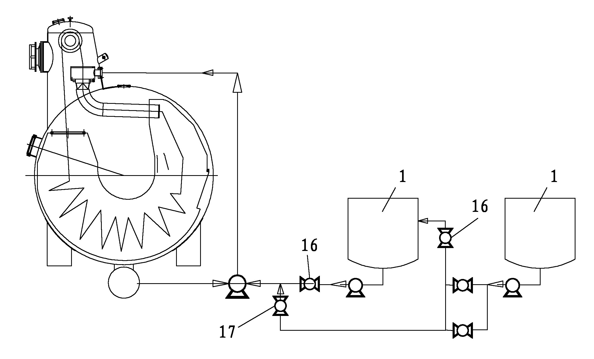
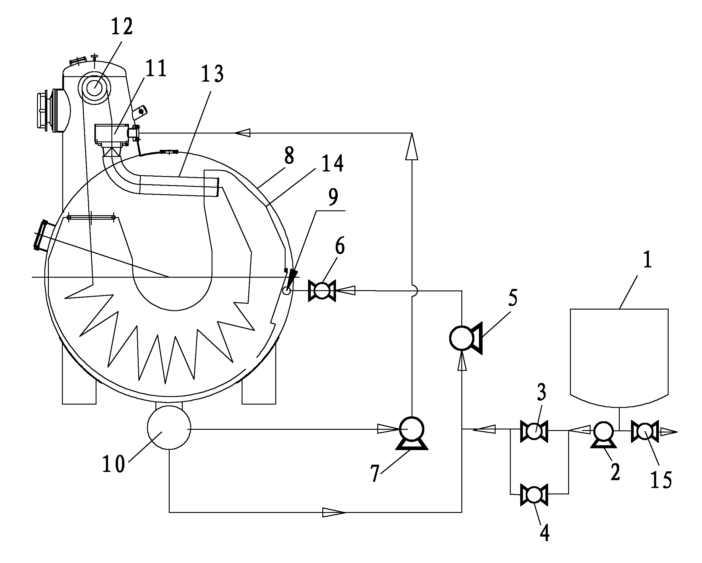
[0026] Such as figure 2 The feeding system of the UF and UFH machine dyeing machines includes a paint bucket, a feed pump, a feed valve, a quantitative valve, a feed pump, a feed valve, a main pump and a dyeing machine, and the paint bucket is connected to the feed pump. The injection valve is connected in parallel with the quantitative valve. One end of the valve unit composed of the two is connected in series with the injection pump, and the other end is connected in series with the feeding pump. The liquid outlet at the bottom of the cloth machine is connected to the feeding pump; the liquid outlet at the bottom of the cloth dyeing machine is also connected to the main pump, and the main pump is connected to the front nozzle on the top of the cloth dyeing machine;

[0027] The feeding system of the dyeing machine includes three flow paths:

[0028] The first flow ...


PUM


Abstract

The invention discloses a charging system of a cloth dyeing machine. The system comprises a paint bucket, a filling pump, a filling valve, a proportional valve, a charging pump, a charging valve, a main pump and a cloth dyeing machine, wherein the paint bucket is connected with the filling pump; the filling pump is connected in parallel with the filling valve and the proportional valve; the filling valve and the proportional valve are connected in parallel with the charging pump; the charging pump is connected with the charging valve; the charging valve is connected with a spraying pipe at the middle part in the cloth dyeing machine; a liquid outlet at the bottom of the cloth dyeing machine is connected with the charging pump and the main pump; and the main pump is connected with a front nozzle at the top of the cloth dyeing machine. The charging system disclosed by the invention has a reasonable structure, reduces the dyeing cost, shortens the technological time and improves the production efficiency.

Description

technical field [0001] The field to which the invention belongs: dyeing and finishing machinery, in particular to a feeding system for a cloth dyeing machine. Background technique [0002] Traditional feeding systems such as figure 1 Shown: including 2 paint buckets, 2 injection pumps, injection valves, 2 injection valves, metering valves, shut-off valves, main pumps and cloth dyeing machines, the structure is complex and the production cost is high. [0003] There are three flow paths: the first paint bucket → the second paint bucket → the front nozzle; [0004] The first paint bucket → front nozzle; [0005] Liquid outlet at the bottom of the dyeing machine → front nozzle. [0006] Wherein the first and second flow paths, the high-concentration dye solution directly leads to the front nozzle, and then the front nozzle contacts the cloth immediately after spraying out, which easily leads to the phenomenon of dyeing the patterned cloth. If you want to avoid the phenomeno...

Claims


Application Information

Patent Timeline
Patent Type & Authority Patents(China)
IPC IPC(8): D06B23/00
Inventor 郑永忠陈红军
Owner FOSHAN SON TECH PRECISION MACHINERY
Why Eureka
Try Eureka