Method for densely building hydroelectric power station and hydroelectric power station capable of being densely built

A construction method and technology for power stations, applied in hydroelectric power stations, hydroelectric power generation, traditional hydropower energy, etc., can solve problems such as river currents and inability to build hydropower stations

Active Publication Date: 2012-06-20
李建英
View PDF4 Cites 2 Cited by
  • Summary
  • Abstract
  • Description
  • Claims
  • Application Information

AI Technical Summary

Problems solved by technology

[0004] The present invention provides a method for densely building hydropower stations and a hydropower station that can be densely built different from existing hydropower methods. The dense construction of hydropower stations in the river can make the limited water resources fully or doubled, and it can also solve the problem that some plain areas have rivers but cannot build hydropower stations.

Method used


Image

  • Method for densely building hydroelectric power station and hydroelectric power station capable of being densely built
  • Method for densely building hydroelectric power station and hydroelectric power station capable of being densely built
  • Method for densely building hydroelectric power station and hydroelectric power station capable of being densely built

Examples


Embodiment 1

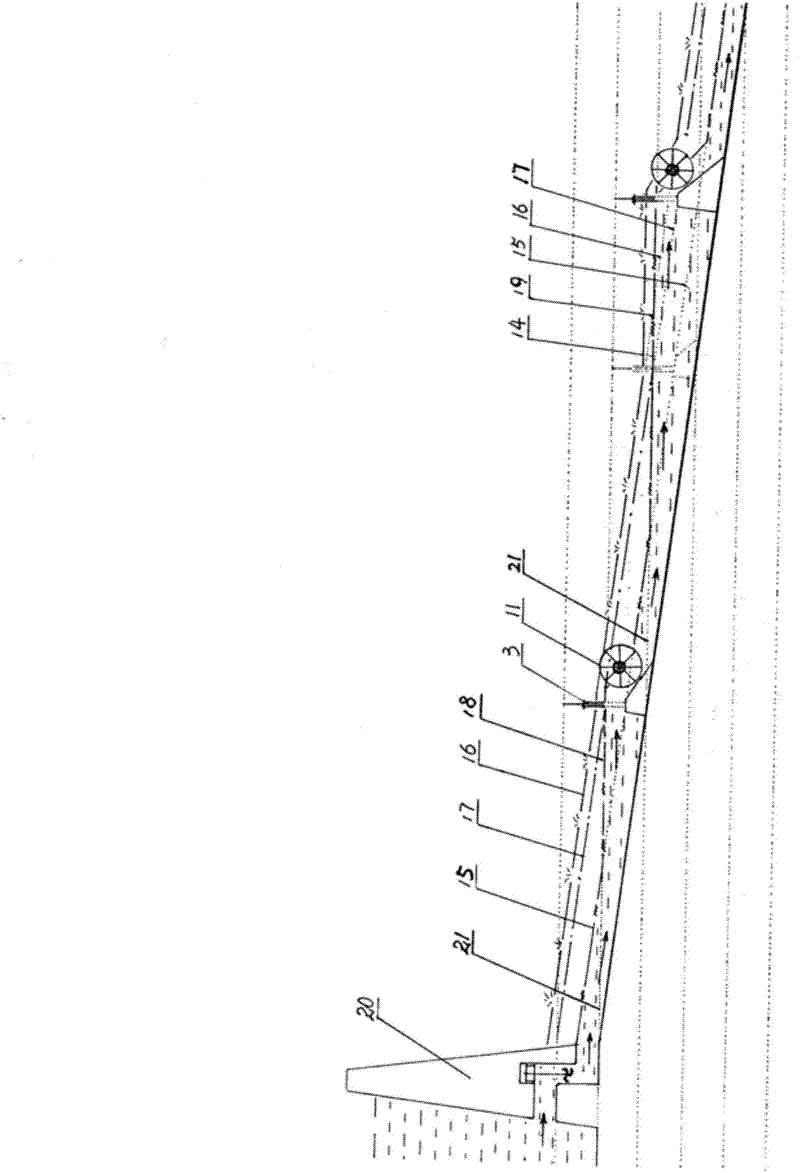
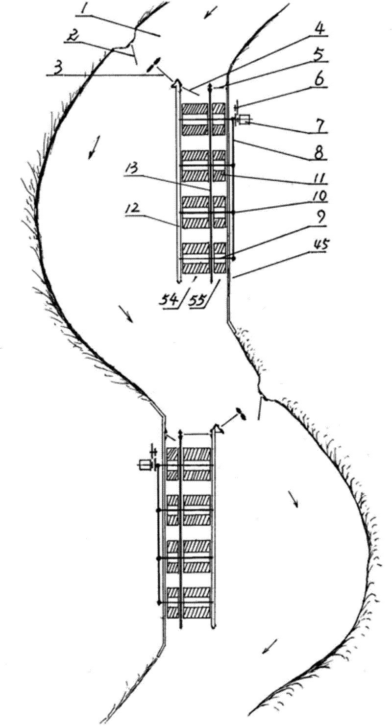
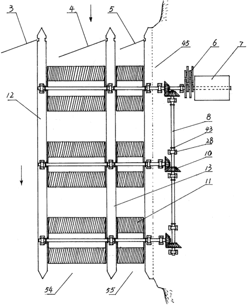
[0025] Embodiment 1: refer to figure 1 , figure 2 , image 3 , Figure 5 , Figure 8 , Figure 9 , a water conservancy power station, including a water turbine 11, a water turbine drive shaft 9, a reversing drive shaft 8, a speed change wheel set 6, and a generator set 7, it also includes first and second shunt gates 2, 3, first and second Two flush gates 5,4, river bank cement platform 45, first and second cement partition walls 13,12 and first and second water diversion channels 55,54 formed by the first and second cement partition walls 13,12 ; The first and second diversion gates 2,3 and the first and second flush gates 5 and 4 are successively built on the upstream end of the river or river 1 in the water direction, and the first and second diversion gates 2 and 3 Or the positions of the first and second flushing gates 5 and 4 can be located on the left or right bank of the river or river 1 according to specific terrain and needs, and they cover the entire width of...

Embodiment 2

[0027] Embodiment 2: refer to figure 1 , Figure 8 , Figure 10 , Figure 11 , Figure 12 , a water conservancy power station, comprising a water turbine 11, a water turbine drive shaft 9, a reversing drive shaft 8, a speed change wheel set 6, a generator set 7, a first shunt gate 2, the first, second, and third flush gates 5, 4, 57, the river bank cement platform 45, the first, second and third cement separation walls 13, 12, 58 and the first and second separation walls formed by the first, second and third cement separation walls 13, 12, 58 2. The third diversion trough 55, 54, 56; the first diversion gate 2 and the first, second and third flushing gates 5, 4, 57 are built on the upstream end of the river or river 1 in the water direction, the The position of the first diversion gate 2 or the first, second and third flushing gates 5, 4, 57 can be located on the left or right bank of the river or river 1 according to specific terrain and needs, and they cover the entire ...

Embodiment 3

[0028] Embodiment 3, with reference to Figure 10 , Based on Embodiment 2, the first diversion gate 2 described in Embodiment 2 forms a diversion tank 22, and the upstream and downstream sections of the diversion tank 22 are respectively equipped with upper and lower navigation gates 23,24. This embodiment is suitable for building in large and medium-sized river sections where ships navigate, and the original lift-type first diversion gate 2 is converted into sliding door-type upper and lower navigation gates 23, 24 for flood discharge and diversion during the flood season. It can also be used as a passage for ships when the river flow is normal.


PUM


Abstract

The invention relates to a method for densely building hydroelectric power stations. The bottom line of a water outlet at a built or previous hydroelectric power station or a bottom line of a river bed as a starting line, the line is horizontally extended to a point at which a next section of a river channel and a flood-season water level line are intersected, and another hydroelectric power station can be built at the point. The hydroelectric power station capable of being densely built comprises water turbines, a generator set and a transmission mechanism which is connected with the water turbines and the generator set. The hydroelectric power station additionally comprises a first bypass gate, a second bypass gate, a first flushing gate, a second flushing gate, a first separation wall, a second separation wall, and a first flume and a second flume which are formed by the first separation wall and the second separation wall, wherein the first bypass gate, the second bypass gate, the first flushing gate and the second flushing gate are sequentially built at the upstream end in the inflow direction of a river, and the first separation wall and the second separation wall are built at the downstream ends of the first flushing gate and the second flushing gate. The water turbines are arranged in the first flume and the second flume. The transmission shafts of the transverse water turbines are mutually connected and then are connected with the transmission mechanism.

Description

technical field [0001] The invention relates to the technical field of hydropower generation, and specifically refers to a method for densely building a hydropower station and an intensively built hydropower station capable of generating electricity by directly installing water turbines on the water surface without blocking rivers and building dams. Background technique [0002] The energy water used by existing hydropower stations is all disposable, that is, after the water flows out of the power station, the water will flow along the river for tens or hundreds of kilometers to the next hydropower station or directly into the sea. Due to various conditions or reasons, it is no longer possible to block the river and build dams to build hydropower stations, which will cause infinite waste of limited water resources. [0003] However, the existing hydropower stations basically select suitable locations on the river to block the river and build dams, install the water turbines ...

Claims


Application Information

Patent Timeline
Patent Type & Authority Applications(China)
IPC IPC(8): E02B9/00E02B9/04
CPCY02E10/22Y02E10/20
Inventor 李建英李盈
Owner 李建英
Why Eureka
Try Eureka