Laser-probe-array-based three-dimensional measurement method and device

A laser probe and three-dimensional measurement technology, applied in the field of three-dimensional measurement, can solve the problems of long processing time, inability to perform stereo matching, interference by laser noise and vibration, etc.

Inactive Publication Date: 2012-06-20
李志扬
View PDF5 Cites 25 Cited by
  • Summary
  • Abstract
  • Description
  • Claims
  • Application Information

AI Technical Summary

Problems solved by technology

At present, there are many measurement methods for depth information or three-dimensional coordinates, but they cannot fully meet the above requirements in terms of measurement speed, or measurement range, or measurement accuracy, or anti-interference.
For example, measurement technology based on laser triangulation and laser scanning technology based on time-of-flight generally use point-to-point measurement methods, which cannot quickly provide large-area three-dimensional coordinates; although laser interferometry technology has high precision, it is prone to interference by laser noise and vibration. Mor

Method used


Image

  • Laser-probe-array-based three-dimensional measurement method and device
  • Laser-probe-array-based three-dimensional measurement method and device
  • Laser-probe-array-based three-dimensional measurement method and device

Examples


Embodiment 1

[0057] A three-dimensional measurement method based on a laser probe array includes the following steps:

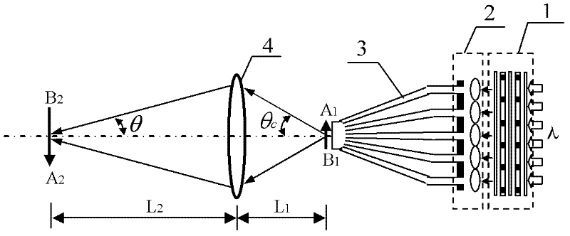
[0058] Step 1. Set the optical center of the optical lens of the two-dimensional camera as the origin of coordinates. The optical axis of the optical lens of the two-dimensional camera is the Z axis, the X axis is perpendicular to the Z axis, the X axis and the Z axis plane is a horizontal plane, and the Y axis is perpendicular to X. Axis Z-axis plane; set the first laser probe generator on the X axis, the optical axis of the first laser probe generator is parallel to the Z axis, the two-dimensional camera monitors the laser probe emitted by the first laser probe generator The reflection on the surface of the object under test, where the first laser probe generator is a digital optical phase conjugate device or a holographic reconstruction device;

[0059] Step 2. Set the predetermined focus point of the laser probe array emitted by the first laser probe generator on the prede...

Embodiment 2

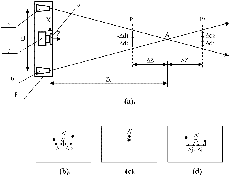
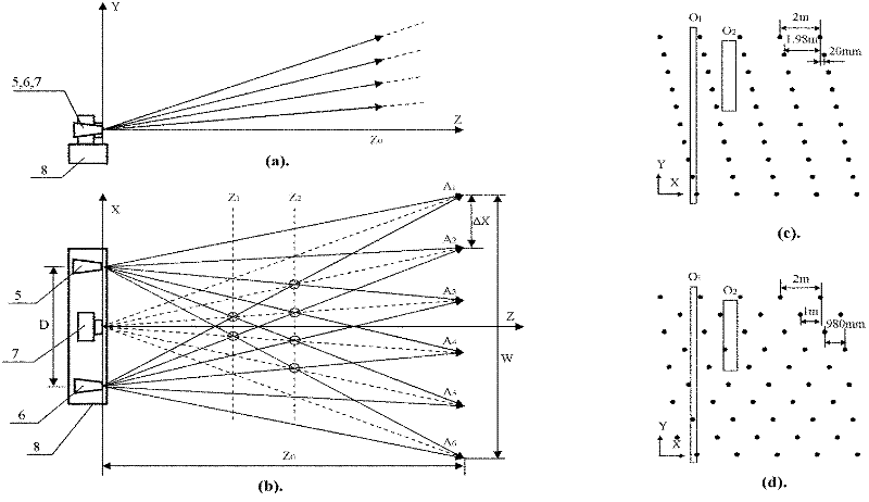
[0081] Such as figure 2 , image 3 As shown, a three-dimensional measurement device based on a laser probe array includes a first laser probe generator 5, a second laser probe generator 6, a first two-dimensional camera 7 and a first holder 8, and a first laser probe The needle generator 5, the first two-dimensional camera 7, and the second laser probe generator 6 are fixed on the first bracket 8 at an equal distance in turn. The optical axis of the first laser probe generator 5 and the second laser probe generator The optical axis of 6 and the optical axis of the first two-dimensional camera 7 are parallel to each other and are located on the same plane. The connection between the optical centers of the first laser probe generator 5 and the second laser probe generator 6 is perpendicular to their optical axes , The optical center of the lens of the first two-dimensional camera 7 is located on the line connecting the optical centers of the first laser probe generator 5 and the ...

Embodiment 3

[0110] Such as Figure 4 , Figure 5 As shown, a three-dimensional measurement device based on a laser probe array includes a third laser probe generator 10, a fourth laser probe generator 11, a second two-dimensional camera 13, a second movable support 12 and a third The movable support 14, the third laser probe generator 10 and the fourth laser probe generator 11 are fixed on the second movable support 12, the third laser probe generator 10 and the fourth laser probe generator 11 The optical axes are parallel to each other, and the connection of their optical centers is perpendicular to their optical axis. The second two-dimensional camera 13 is fixed on the third movable support 14, the second movable support 12 and the third movable support 14 Both are provided for aligning the optical axis of the second two-dimensional camera 13, the optical axis of the third laser probe generator 10, and the optical axis of the fourth laser probe generator 11 on the same plane and parallel...


PUM


Abstract

The invention relates to a laser-probe-array-based three-dimensional measurement method and a laser-probe-array-based three-dimensional measurement device and belongs to the field of three-dimensional measurement. Based on the digital optical phase conjugation principle, tens of thousands of laser probes are projected onto preset positions in space, the reflection of the laser probes on the surface of an object is monitored by a common camera and thus, the measurement of a three-dimensional coordinate is realized. The structure and parameters of the laser probe three-dimensional camera vary with application places, the precision of the measurement is improved by regional measurement, and a precision three-dimensional coordinate in a large region or 360-degree range can be obtained by combining the results of the regional measurements. The method and the device are suitable to be used in field of robot, intelligent driving, obstacle quick detection and high-precision industrial part automatic measurement and the like.

Description

Technical field [0001] The invention belongs to the field of three-dimensional measurement, and more specifically relates to a three-dimensional measurement method based on a laser probe array, and also relates to a three-dimensional measurement device based on a laser probe array. It is suitable for rapid 3D coordinate measurement of robots, intelligent driving and obstacle detection, and 3D measurement of static high-precision industrial parts. Background technique [0002] Ordinary cameras project objects onto the image surface through an optical lens, and use film or CCD / CMOS image sensors to record, so the photos taken are two-dimensional, and the depth information is lost. However, with the rapid development of intelligent robots and safe unmanned driving, the demand for depth information is increasing, and there is an urgent need to quickly collect three-dimensional coordinate information of the scene. At present, there are many methods for measuring depth information or ...

Claims


Application Information

Patent Timeline
IPC IPC(8): G01B11/24G01B11/00
Inventor 李志扬
Owner 李志扬
Why Eureka
Try Eureka