Three-degree-of-freedom integrated stick-slip linear positioning device

A positioning device, stick-slip technology, applied in the direction of measuring devices, instruments, nanotechnology, etc., can solve the problems of large volume, low positioning accuracy, large assembly error, etc., to achieve small volume, high positioning accuracy, large output force Effect

Inactive Publication Date: 2012-06-20
HARBIN INST OF TECH
View PDF5 Cites 10 Cited by
  • Summary
  • Abstract
  • Description
  • Claims
  • Application Information

AI Technical Summary

Problems solved by technology

[0003] The purpose of the present invention is to solve the problems of large volume, large assembly error and low positioning accuracy existing in the existing positioning device, and further provide a three-degree-of-freedom integrated stick-slip linear positioning device

Method used


Image

  • Three-degree-of-freedom integrated stick-slip linear positioning device
  • Three-degree-of-freedom integrated stick-slip linear positioning device
  • Three-degree-of-freedom integrated stick-slip linear positioning device

Examples


specific Embodiment approach 1

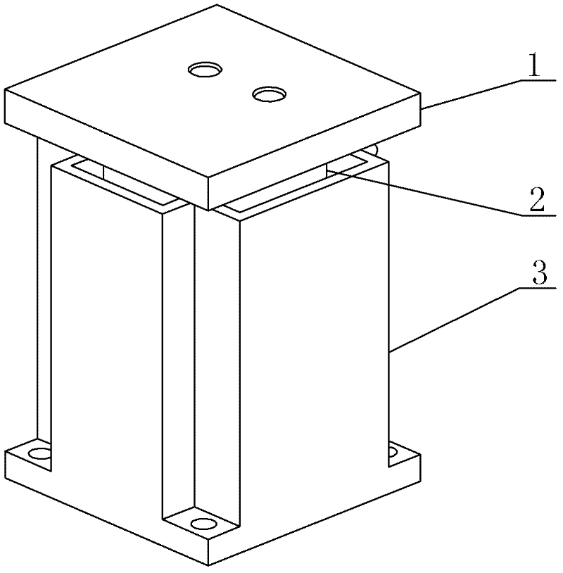
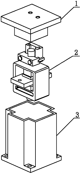
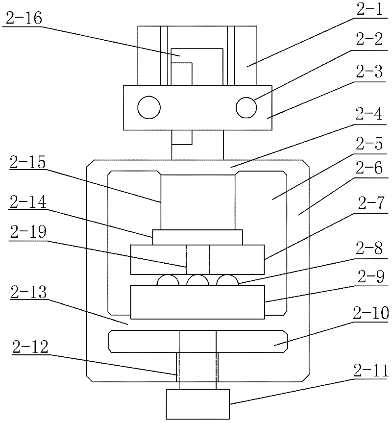
[0009] Specific implementation mode one: combine Figure 1 to Figure 9 Describe this embodiment. The three-degree-of-freedom integrated stick-slip linear positioning device of this embodiment includes a bearing cover 1, a drive unit 2 and a base 3. The bearing cover 1 includes a bearing plate 1-1 and a drive unit 2 The matching cover 1-2, the cover 1-2 is fixed on the plate surface of the bearing plate 1-1, and the drive unit 2 includes a first pressing block 2-2, a second pressing block 2-1, Elastic driving seat 2-6, piezoelectric ceramic driver 2-15, guide column 2-16, contact foot 2-14, displacement plate 2-7, pre-tightening pressure plate 2-9 and a plurality of balls 2-8, described The elastic drive seat 2-6 is a drive seat with a square cavity 2-5, and the first briquetting block 2-2 and the second briquetting block 2-1 are all arranged on the upper elastic plate 2-4 of the elastic drive seat 2-6 Above, the guide post 2-16 is clamped between the second press block 2-1 an...

specific Embodiment approach 2

[0010] Specific implementation mode two: combination image 3 To illustrate this embodiment, the shape of the tentacles 2-14 described in this embodiment is flat or hemispherical. Such setting meets the design requirements. Others are the same as in the first embodiment.

specific Embodiment approach 3

[0011] Specific implementation mode three: combination Figure 5 To illustrate this embodiment, the number of blind holes 2-18 described in this embodiment is four, and the four blind holes 2-18 are arranged in a cross shape on the upper end surface of the pre-tightening platen 2-9, and the four blind holes The sides of the quadrilateral formed by the centers of 2-18 are equal. Such setting effectively reduces the frictional force when the displacement plate moves and meets the design requirements. Others are the same as in the first or second embodiment.


PUM


Abstract

A three-degree-of-freedom integrated stick-slip linear positioning device relates to a positioning device and solves the problems that existing positioning devices are large in size, high in assembling error and low in positioning precision. The Three-degree-of-freedom integrated stick-slip linear positioning device comprises a bearing plate and a cap matched with a driving unit. The cap is fixedly connected to a surface of the bearing plate. The driving unit comprises a first press block, a second press block, an elastic driving base, a piezoelectric ceramic driver, a guide pillar, a contact, a shifting plate, a pretightened press plate and multiple balls, the upper end face of the piezoelectric ceramic driver is connected with the lower end face of the upper elastic plate of the elastic driving base, the lower end face of the piezoelectric ceramic driver is connected with the upper end face of the contact, the lower end face of the contact is connected with the upper end face of the shifting plate, the lower end face of the pretightened press plate is connected with the upper end face of a lower elastic plate of the elastic driving base, and two longitudinal ends of the shifting plate are disposed outside a square cavity of the elastic driving base and detachably connected with a base respectively. The three-degree-of-freedom integrated stick-slip linear positioning device is used for positioning articles.

Description

technical field [0001] The invention relates to a positioning device. Background technique [0002] Nanopositioning technology is the basis of nanomanipulation technology. With the rapid development of nanotechnology, more and more application fields require multi-degree-of-freedom positioning devices with small size, nanometer-level positioning accuracy and millimeter-level motion range. At present, most of these positioning devices adopt the stick-slip driving method, that is, the dynamic and static friction between the contact surfaces of the objects is used to realize the step displacement. When the friction between the contact surfaces is static friction, the relative displacement of the two objects does not occur; when the friction between the contact surfaces When the force is dynamic friction, the relative displacement of the two objects occurs, and the switching of the friction state can be realized by controlling the relative speed between the objects. When the re...

Claims


Application Information

Patent Timeline
Patent Type & Authority Applications(China)
IPC IPC(8): G01B21/02B82B3/00B82Y40/00
Inventor 荣伟彬张世忠王乐锋孙立宁
Owner HARBIN INST OF TECH
Why Eureka
Try Eureka