Method and device for automatically and synchronously positioning high-speed rotating blades

An automatic synchronization and high-speed rotation technology, applied in the direction of measuring devices, instruments, etc., can solve the problems of manual modification of shafts or blades or adding accessories, restrictions on the wide use of measurement systems, and system malfunctions, etc., to meet real-time online monitoring and matching The effect of high speed and broad application range

Inactive Publication Date: 2012-06-20
TIANJIN UNIV
View PDF5 Cites 9 Cited by
  • Summary
  • Abstract
  • Description
  • Claims
  • Application Information

AI Technical Summary

Problems solved by technology

[0003] Usually, the non-contact rotating machinery blade parameter measurement system needs to add a synchronous sensor to monitor the rotating shaft or make a synchronous mark on a certain blade, and use the synchronous signal as a reference to distinguish the one-to-one correspondence between the measurement information and the actual blade, otherwise It weakens the role that the measurement system can play, and even makes the system not work properly [5-9]
On the other hand, the harsh working conditions of some large-scale machinery do not allow manual modification or addition of accessories to the shaft or blade, which limits the wide use of the measurement system to a certain extent.

Method used


Image

  • Method and device for automatically and synchronously positioning high-speed rotating blades
  • Method and device for automatically and synchronously positioning high-speed rotating blades
  • Method and device for automatically and synchronously positioning high-speed rotating blades

Examples


Embodiment Construction

[0048] The technical solution adopted by the present invention is an automatic synchronous positioning method for high-speed rotating blades, which includes the following steps:

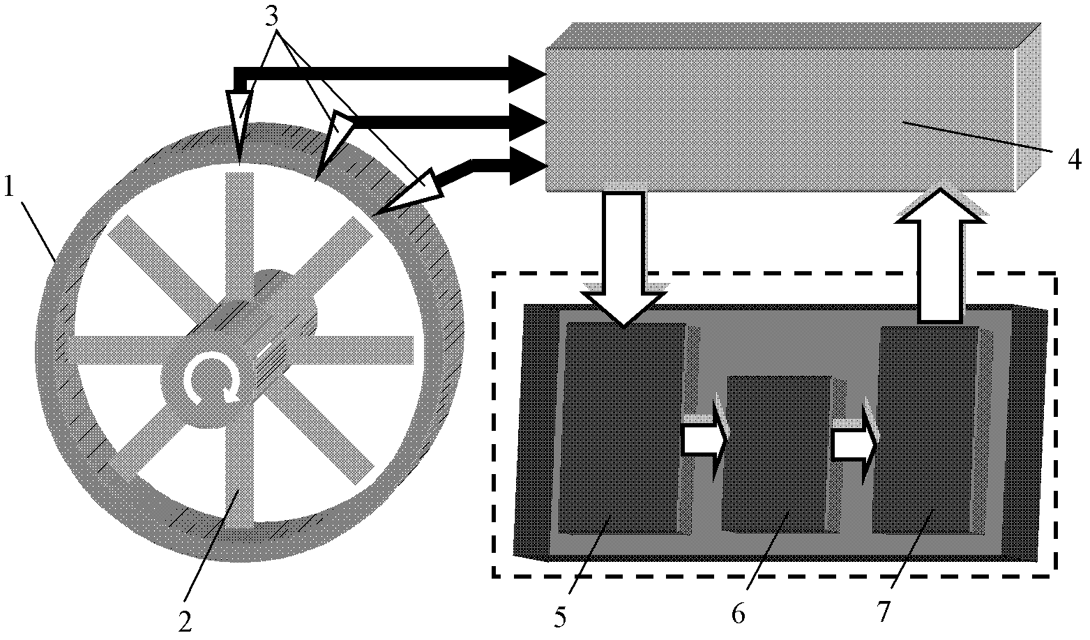
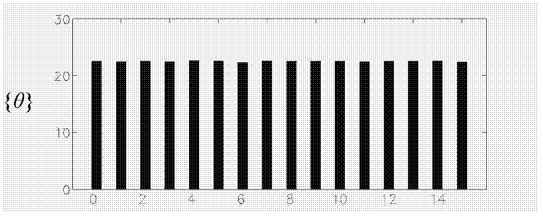
[0049] The angles between N adjacent blades of the rotor measured during installation, shutdown, maintenance or commissioning of the rotor form a {θ} sequence, {θ}=(θ 0 , θ 1 ,...,θ i ,...,θ N-1 ), where i is the set blade number. When i is greater than or equal to 1, θ i is the angle between blade i and blade i-1, θ 0 is the angle between No. 0 blade and No. N blade. The sequence {θ} is used as a matching template, and this template is definite and unique for a specific rotating mechanical rotor.

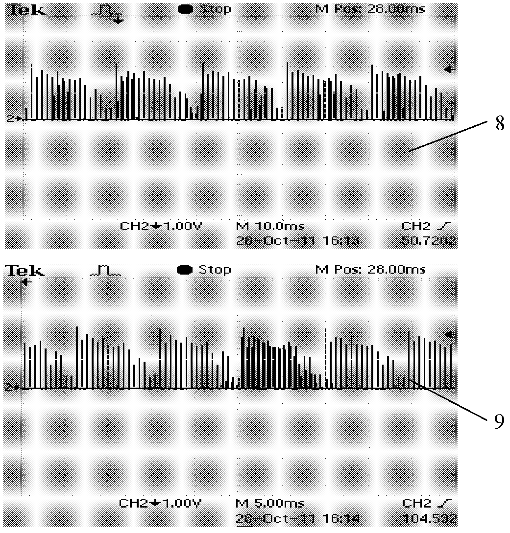
[0050] The effective signal sequence {V} continuously output by the non-contact sensor is transmitted to the high-precision blade tip timing module to obtain the blade arrival time sequence {t}.

[0051] The signal processing module converts the time series {t} into the angle sequence between the c...


PUM


Abstract

The invention mainly relates to the field of non-contact large rotary mechanical high-speed rotating blade parameter measurement technologies and intelligent fault diagnosis systems, in particular to a method for automatically and synchronously positioning the high speed blades \by directly transforming and matching signals output by the conventional non-contact sensor. The method is suitable for a parameter non-contact online measurement system for most of rotary mechanical rotor blades. In order to fulfill the aim, the technical scheme provided by the invention is that: a device for automatically and synchronously positioning the high-speed rotating blades comprises a non-contact sensor for measuring a blade arrival signal, a high-precision blade tip timing module for receiving the signal output by the non-contact sensor to obtain a blade arrival time sequence {t}, and a signal processing module for performing algorithm transformation to obtain an included angle sequence {phi}. The method and the device are mainly applied to large rotary mechanical high-speed rotating blade parameter measurement occasions.

Description

technical field [0001] The invention mainly relates to the field of non-contact large-scale rotating machinery high-speed rotating blade parameter measurement technology and an intelligent fault diagnosis system. The invention relates to a corresponding matching method between blade parameters measured by the measurement system and specific blades. Specifically, it relates to a method and a device for automatic synchronous positioning of high-speed rotating blades. Background technique [0002] Aeroengines, gas turbines, steam turbines, flue gas turbines, blowers and other large rotating machinery are key equipment in aviation, ship, electric power, petrochemical, metallurgical and other systems. As the core component of the rotor of a large rotating machine, the blade itself vibrates and changes in various operating parameters (such as blade tip clearance) caused by the vibration of the rotor affect the normal operation and work efficiency of the entire system. Real-time m...

Claims


Application Information

Patent Timeline
Patent Type & Authority Applications(China)
IPC IPC(8): G01D21/02
Inventor 段发阶叶德超李扬宗郭浩天欧阳涛
Owner TIANJIN UNIV
Why Eureka
Try Eureka